The Tide-Predicting Machine
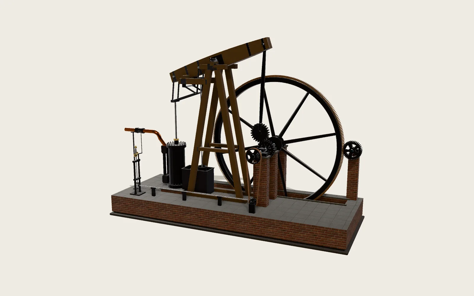
The tide at a port can be taken apart into many rises and falls with fixed periods, each set by some motion of the Moon or the Sun. In 1872 William Thomson, later Lord Kelvin, designed a machine that made each of them a crank, added them with one wire and drew the sum with a pen on a band of paper. For more than ninety years afterwards, most of the world’s tide tables came from machines like it.
Scroll
A Port Needs a Table
Ships come and go by the depth of water, and the depth changes with the tide twice a day. A port needs to know the times and heights of high and low water for every day of the coming year.
The harmonic method writes a port’s tide as a sum of cosines. The period of each comes from astronomy; its amplitude and phase come from analysing that port’s tide-gauge records. As the US Coast and Geodetic Survey later put it, without a predicting machine the harmonic method would involve too much labour to be of practical service.
The catalogue of the 1876 South Kensington exhibition said of Kelvin’s first machine that it could be turned fast enough to run off a year’s tides for any port in about four hours.
Many Rises and Falls, Added
The Moon makes the sea rise and fall once every 12.42 hours: this term is called M2. The Sun’s term takes exactly 12 hours: S2. Now in step and now opposed, they make the range grow and shrink over about 14.8 days: spring tides and neap tides.
The Moon’s eccentric orbit and the Moon and Sun moving off the equator add more terms with slightly different periods: N2, K2 and L2 near half a day, K1, O1 and P1 near a day. Shallow water makes terms of a quarter day, such as M4 and MS4. Kelvin’s first machine carried these ten.
Their sizes differ from port to port. In NOAA’s figures, Boston’s M2 is 1.37 m and its K1 only 0.14 m: two highs and two lows a day. At Pensacola on the Gulf of Mexico, M2 is 1.7 cm while K1 and O1 are about 12 cm each: on most days the tide rises and falls only once.
One Crank per Term
Each term is a turning gear wheel with a crank pin on its face. The pin runs in a horizontal slot on a rod that can only slide up and down: as the wheel turns evenly, the rod moves up and down as a cosine. This is a crosshead and slide, a Scotch yoke.
How far the pin sits from the axis is the term’s amplitude; the angle the wheel is set to before the run is its phase. A new port means setting these twenty numbers again.
On the first machine the pulleys rode on the cranks themselves and moved in circles, with a small geometric error. Kelvin’s later machines used the crosshead and slide, so the motion is an exact cosine.
Tooth Counts Set the Speeds
Every term must turn exactly as fast as it does in the sky. M2 turns 28.9841042 degrees an hour, just short of S2’s 30, and that small difference is what makes springs and neaps.
On the US Coast and Geodetic Survey’s Machine No. 2 every shaft turns 30 degrees an hour, then drives through two pairs of gears: for M2, 30 × 103/74 × 59/85 = 28.9841017 degrees an hour, 0.02 degree out in a year. The tooth counts come from writing each speed ratio as two fractions and picking the nearest pair.
With the cast-iron front frame cut away, the bevel gears on the main shaft hand the motion to every spindle.
M2: 30 × 103/74 × 59/85 = 28.9841017 °/h
One Wire Does the Sum
The cranks stand in two rows, an upper and a lower; each rod ends in a pulley, and all the pulleys lie in one plane. A fine steel wire, fixed at one end, runs over an upper pulley and under a lower one in turn, every free length of it vertical; the other end carries the pen.
When an upper pulley rises, or a lower one falls, the wire round it takes up twice that length, so the hanging pen rises twice as far. With all ten moving, the pen’s height is twice the sum of the ten terms. The idea of a chain over pulleys for adding came from Wheatstone; Kelvin used a wire instead.
A Pen Draws the Year
Kelvin wrote that the hanging weight is an ink bottle with a glass tubular pen, which marks the tide level in a continuous curve on a long band of paper, moved horizontally by a vertical cylinder geared to the shafts.
At about a foot a day, a year’s curve is 365 feet long. Machine No. 2 was cranked at 20 turns a minute, six turns to a machine day, so tracing a year took about 1 hour 50 minutes; with the reading and copying, a port’s year took 10 to 15 hours.
Taken Apart
The first machine was made in 1872–73 by A. Légé and Co. of London: 1.82 m long, 1 m wide, 0.77 m high and 86 kg. It is in the Science Museum, London. The arithmetic of its gearing was Edward Roberts’.
Later machines grew. Machine No. 2 in the United States is about 11 feet long and 6 feet high, carries 37 terms and weighs about 2,500 pounds. It has a second crank on every shaft, set 90 degrees ahead and summed on its own chain, so it stops at the times of high and low water.
“Position Z”, 1944
On 9 October 1943, Commander Farquharson of the Admiralty’s Tidal Branch sent Arthur Doodson at the Liverpool Tidal Institute 11 pairs of harmonic constants for a place named only “Position Z”, and asked for hourly heights for four months from 1 April 1944. It was Normandy.
The landings had to start an hour after first light at low water, so the engineers could see and clear the obstacles on the beach. Low water came at different times on the five beaches: more than an hour apart between Utah and Sword, about 100 km apart. Only 5, 6 and 7 June 1944 met every condition. Doodson used the Institute’s two machines: one of Kelvin’s type and one designed by Roberts.
What It Changed
Only about thirty machines of this kind were ever made, for Britain, the United States, Germany, France, Japan, India, Brazil and others. Every US tide table from 1912 to 1965 came from Machine No. 2; from 1966 electronic computers took over. A German machine built in 1935–39 carried 62 terms.
The machines retired; the method did not. Tide tables are still made by adding a port’s few dozen harmonic constants at the speeds astronomy gives, only now a computer turns the crank.
Turn It Yourself
Pick a port, and the cranks’ lengths and angles change to its harmonic constants. Take a term out, and its pin slides back to the axis and the curve loses it. The readouts are the machine’s next high and low water.
Try thisLeave only the M2 and S2 cranks and run the machine for half a month: how do the swings of the pen grow and shrink, and how many days apart are the biggest?
What the model leaves out
This is not a copy of any one machine. The layout, sizes and look of the frame are ours, laid out on the principles of Kelvin’s machines: the ten terms of his first machine, the crosshead and slide of his later ones, a band pulled by a vertical cylinder. The tooth counts are Machine No. 2’s (the first machine used Légé’s worm gearing, and its tooth counts were not published); on No. 2 upright shafts turn at 30 degrees an hour and each term takes two pairs of gears from them; the model draws the first pair as bevel gears on the main shaft and the second as the crank wheel and its pinion. The band runs much slower than on the originals, so a few days fit on the screen; the originals marked each hour on the paper, the model’s band has printed day lines. The harmonic constants are NOAA’s; the amplitudes carry the node factors for 1 January 2026 and the phases are set for the same moment; there are no long-period terms (Sa, Ssa), so the seasonal change in mean level is not in the curve. Times are each port’s standard time.
Some common misreadings
The machine does not compute the pull of the Moon and the Sun, and knows nothing of the shape of the sea. It only adds cosines of known speeds; how large each term is at a port and how late it runs must first be analysed from about a year of that port’s observations (Kelvin built a separate harmonic analyser for that). Nor is it a programmable computer: a new port means setting the cranks again. The readouts show how far the sum of ten terms is from the sum of thirty-odd.
Sources
- Science Museum, London: William Thomson’s tide predicting machine, 1872 (object 1876-1129; 1820 × 1000 × 770 mm, 86 kg, ten constituents, a year in about four hours)
- The same: model to demonstrate combination of tidal constituents, 1872 (1881-12)
- W. Thomson, The tide gauge, tidal harmonic analyser, and tide predicter (Minutes of Proceedings of the Institution of Civil Engineers, 1881), in Mathematical and Physical Papers vol. 6, pp. 272–305: the ten terms, wire and pulleys, ink bottle and glass pen, the vertical cylinder, Légé and Roberts, the crosshead and slide of machine No. 3
- US Coast and Geodetic Survey, Description of the U.S. Coast and Geodetic Survey Tide-Predicting Machine No. 2 (Special Publication 32, 1915): Table C tooth counts and speeds, 30° an hour shafts, three crank turns to one, 20 turns a minute, the chain’s doubling, dimensions, earlier machines
- NOAA: Tide-Predicting Machine No. 2 (completed 1910, 37 constituents)
- NOAA: History of tide prediction (Machine No. 2 from 1912 to 1965, electronic computers from 1966)
- NOAA CO-OPS: harmonic constants by station (the lab’s six ports)
- P. L. Woodworth, Tide prediction machines at the Liverpool Tidal Institute (History of Geo- and Space Sciences 11, 2020): constituents and dates of the machines, the two used for D-Day
- B. Parker, The tide predictions for D-Day (Physics Today 64(9), 2011): “Position Z”, 11 pairs of constants, the five beaches, 5–7 June
- National Oceanography Centre: Tide predicting machines
- German Maritime Museum, Bremerhaven: the 1915/16 tide calculator
- National Oceanography Centre: constituent speeds
The text, pictures and models on this page are licensed CC BY-NC 4.0: free to use and adapt for teaching and other non-commercial purposes, with credit to world.lapla.si. Third-party material listed above keeps its own licence.
Follow the question
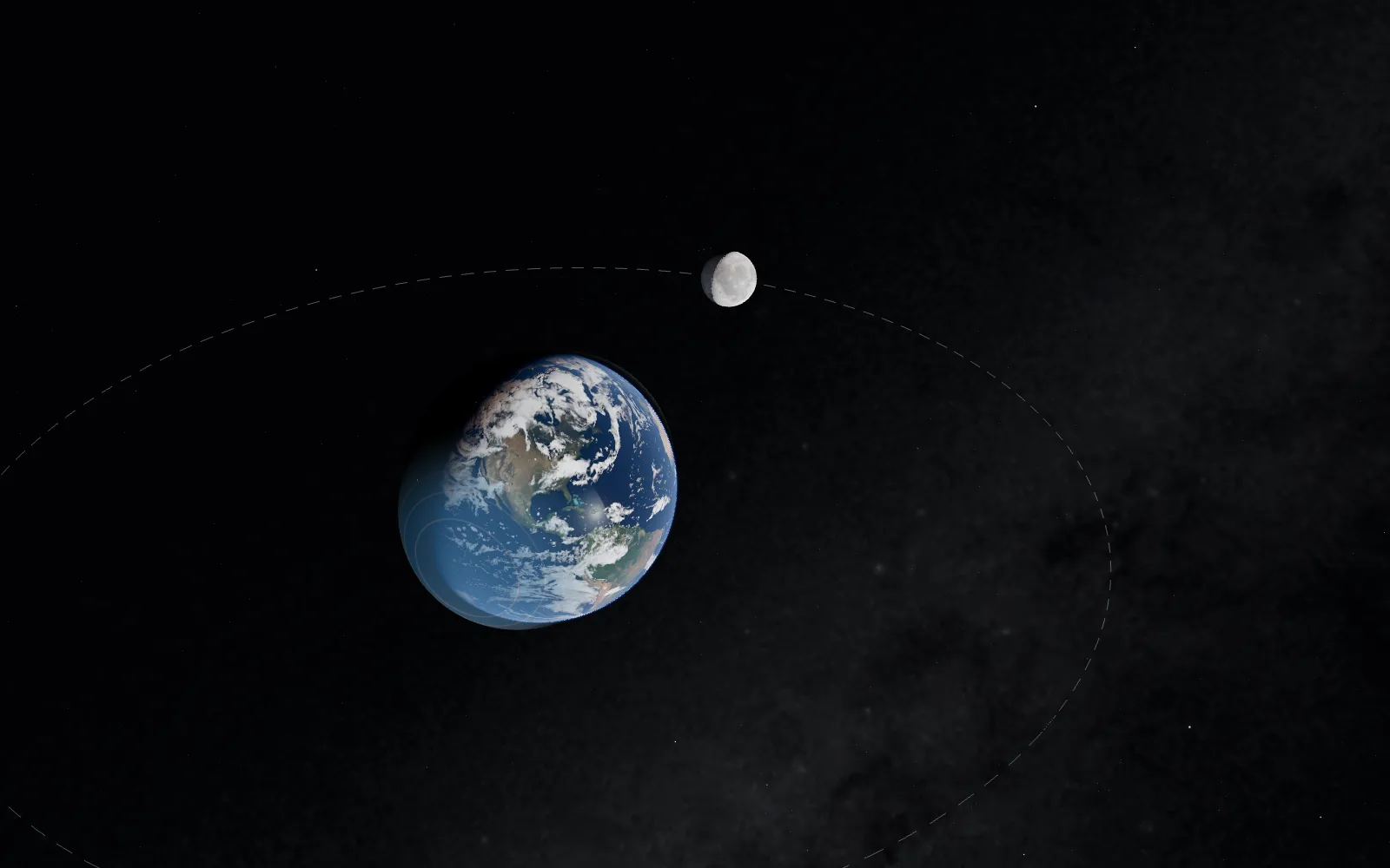 Plate 10How the Moon Moves the SeaWhy are there two high tides a day? Because the Moon pulls the near ocean toward it — and leaves the far ocean behind.
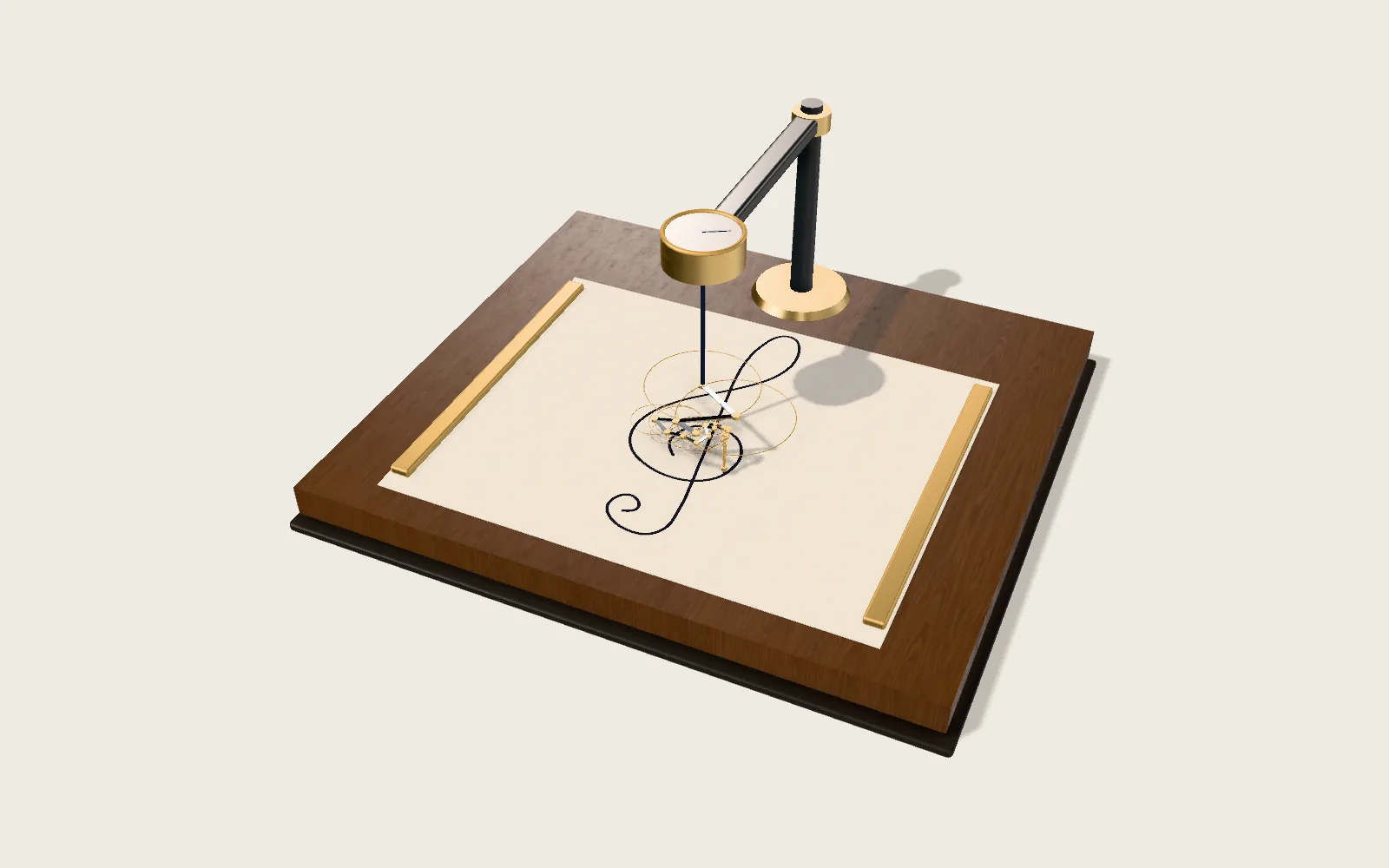 Plate M03Any Closed Line, Drawn by Turning CirclesA chain of arrows, head to tail, each turning at a whole-number speed: the last tip can draw any closed line.
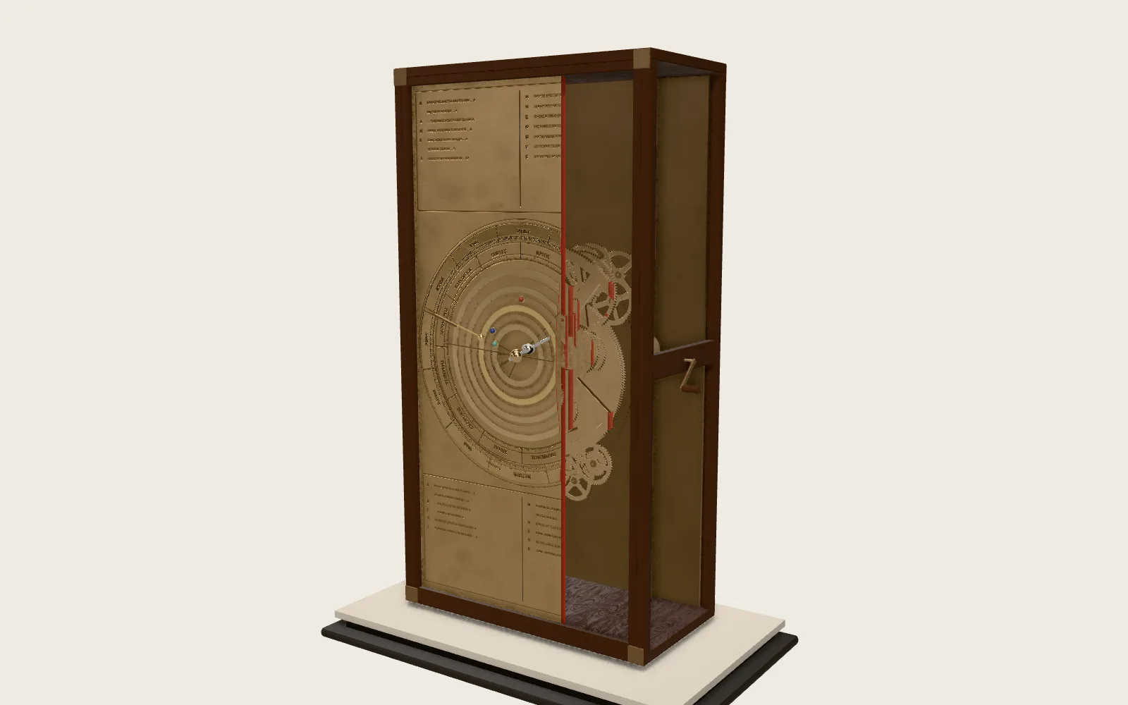 Plate C12The Antikythera MechanismA box of bronze gears from more than two thousand years ago: turn the crank, and the Sun, the Moon, its phase, the calendar and the eclipse cycles all move on together.
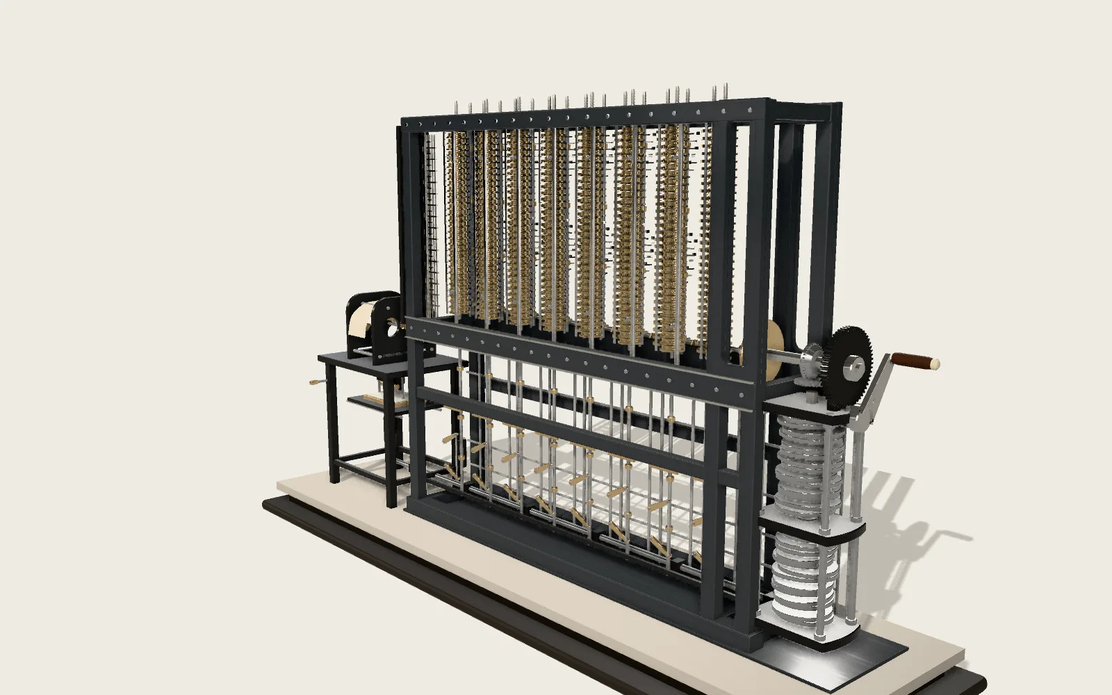 Plate C10The Difference EngineTables of polynomials by addition alone: eight columns of figure wheels, each added to the next, one result per turn of the cycle, printed straight away.