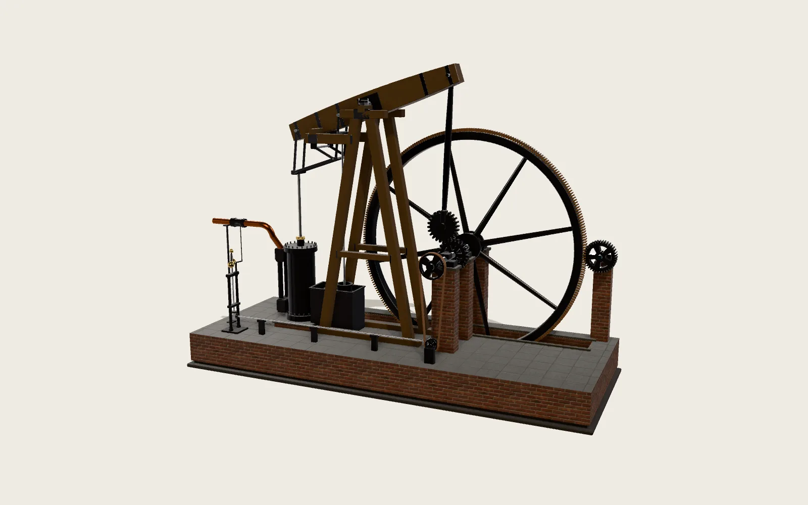
The Difference Engine
Navigation, astronomy and engineering in the nineteenth century ran on printed tables, and the tables were computed, copied and typeset by hand, with errors everywhere. Babbage designed a machine that does nothing but add, and left both the arithmetic and the printing to gears. The model is his Difference Engine No. 2, after the one the Science Museum in London built to his drawings of 1847–49: bronze figure wheels, an iron frame, steel carry arms, the crank and cam stack at one end and the printing and stereotyping apparatus at the other.
Scroll
Errors in the Tables
In the early nineteenth century, logarithms, trigonometric functions and the positions of the planets came from printed tables. Mathematicians, navigators, engineers, surveyors and bankers relied on them. Teams of people computed them by hand, then they were copied, typeset and printed, and every step could go wrong.
In 1821 Babbage and his friend John Herschel were checking a table of astronomical figures computed by hand. There were so many errors that Babbage exclaimed, “I wish to God these calculations had been executed by steam.” He later claimed that errors in tables had cost the government £2–3 million and run ships aground.
Addition Alone
Polynomials have a property: subtract neighbouring values again and again, and the n-th differences of a polynomial of degree n are constant. For x² + x + 41 the values step by 2, 4, 6, 8…, and the steps of those steps are 2 everywhere.
Turn it round: from the first value and its differences, the whole table follows by addition. Add 2 to the first difference, then the first difference to the value. No multiplying, no dividing. The machine only has to add.
The difference table of x² + x + 41: the second differences are all 2, and each new row takes two additions
Eight Columns of Figure Wheels
A number is a column of thirty-one bronze figure wheels, units at the bottom. Each wheel has forty teeth and 0 to 9 engraved four times round its barrel, so one tooth is one unit. An engraved cursor in front points at each digit.
There are eight columns: the result at the far left, then the first to the seventh difference to the right. So it tabulates polynomials up to the seventh order, thirty-one digits each. For lower orders the unused columns hold zero.
Two Halves to a Result
In each addition the wheels of one column turn back to zero and the wheels of the column on its left turn forward as far. This is giving-off; afterwards the number given off is restored. Sector wheels between the columns carry the motion across.
The engine does not add column by column from right to left. A cycle has two halves. In the first, the 7th, 5th, 3rd and 1st differences are added to their left-hand neighbours all at once; in the second, the 6th, 4th and 2nd. The starting values are set offset to suit this rhythm. When the first half ends, the new value stands on the results column.
The crank at the right drives it all. It turns a 14-tooth pinion on a 56-tooth wheel, so four turns of the handle make one cycle, and a stack of 28 cams lifts, turns and shifts the columns’ axes on time.
Carrying Tens
A wheel that passes from 9 to 0 while receiving does not carry at once. It nudges a carry lever beside it into a “warned” position, a note that one is owed to the digit above.
Once the addition is done, the carry axis behind each column turns. Its thirty arms stand in a helix, 22.5° apart, and sweep past the levers one after another from the bottom up: a warned lever moves the wheel above it on by one tooth. If that turns a 9 into a 0, the next lever up is warned, and the next arm deals with it. The carry axis turns twice, so a chain of carries runs all the way to the top.
Printed Straight Away
A set of racks and spindles carries the result across to the output apparatus at the left. Each cycle it prints the result in ink on a paper roll and presses the same digits with punch wheels into soft material in a tray, such as wet plaster of Paris, to make a mould for a printing plate.
It prints and stamps the lower thirty digits. Line spacing, the number of columns and the margins can be set in advance, and the engine stops itself when a page is full. Between the arithmetic and the printed page, no one copies a figure or sets a piece of type.
Taken Apart
At the top are the eight columns of figure wheels, the sector wheel axes between them, and behind them the carry axes with their helical arms. Below are the rods, racks and bell cranks that lift and turn those axes.
At the right is the control unit: the cam stack, the gears and the crank. At the left is the output apparatus: the paper roll, the inking rollers, thirty printing wheels, and below them the stereotype tray and the falling weights that move it. The engine has about 8,000 parts, half in the calculating section and half in the output apparatus.
Built 150 Years Later
Babbage announced the difference engine in 1822. The British government paid for Difference Engine No. 1, made by the toolmaker Joseph Clement. In 1832 a section was assembled, about 2,000 parts and one seventh of the calculating section, and Babbage used it for demonstrations. A dispute stopped the work in 1833; the Treasury had spent £17,500.
From 1847 to 1849 Babbage drew Difference Engine No. 2: a third of the parts of No. 1 for the same power. In 1852 he offered the designs to the government, which turned them down. From 1985 the Science Museum in London built it to the original drawings. The calculating section was finished in 1991, for the bicentenary of Babbage’s birth; the printing and stereotyping apparatus in 2002. It weighs about 5 tonnes and stands 3.4 m long and 2.1 m high. A second engine, built for a private collector, was shown and demonstrated at the Computer History Museum in California from 2008 to 2016.
In Babbage’s lifetime Georg and Edvard Scheutz of Stockholm built working engines on the same principle: a prototype in 1843 and a metal engine in 1853. In 1859 Bryan Donkin and Company of London built one for the British government, which used it to compute the English Life Table of 1864.
What It Changed
Difference Engine No. 2 showed that Babbage’s design works: made to the precision of nineteenth-century workshops, it calculates, and correctly. The builders found one error in the layout of the carry warning as drawn, which would have jammed; they made the odd columns’ mechanism a mirror image, and the design itself was unaffected. That is why the digits on the odd and even columns run in opposite directions.
It turned calculation into a definite mechanical process: a number is a position of wheels, addition is rotation, and carrying has its own time in the cycle. Locks hold every wheel on a whole digit; a wheel caught between two digits jams the engine rather than giving a wrong answer. With these safety devices, Babbage boasted, the engine would break or jam but never deceive. By the time he designed it he had already conceived the far more general Analytical Engine.
Turn It Yourself
Pick a polynomial and turn the crank (or push the lever to let it run), and watch the columns add and the results print. Set one carry lever to “disconnected” and see where the error begins and how it carries on.
Try thisPick x² + x + 41, set the results column’s units-to-tens carry lever to “disconnected” and crank: which result is the first one wrong, and by how much?
What the model leaves out
The overall size, eight columns of thirty-one wheels, forty teeth and four runs of digits, the 14-to-56-tooth reduction, the 28 cams, and the thirty carry arms 22.5° apart follow the Science Museum’s sources; the spacing of the columns, the rods and racks of the lower section and the shape of the output apparatus are drawn in proportion, not from the drawings. The figure wheel locks, the lifting of the axes during giving-off, the drive and warning nibs on the wheels, the reset stops and the cams inside the output apparatus are not shown. On the real engine the digits on the odd and even columns run in opposite directions; in the model they run the same way. The timing within a cycle is simplified, in the order of the museum’s timing diagram: giving-off, then carriage, with the numbers given off restored within the same half-cycle. In the laboratory the results follow the real engine’s rules, but only the lower digits are shown.
Some common misreadings
A difference engine is not a general-purpose computer: it only adds, and only makes tables of polynomials (or of functions approximated by them). Babbage’s programmable general machine was the Analytical Engine, which was never built. Difference Engine No. 2 was not built in Babbage’s lifetime, and only a section of No. 1 was finished. The Science Museum’s engine is not a replica: it is the first complete engine ever built to the design. It is turned by hand, not by steam.
Sources
- Science Museum Group: Difference Engine No. 2 (designed 1847–49, main part completed 1991, printing mechanism added 2002; iron, steel, bronze; 2.1 × 3.4 × 0.5 m; figure wheel 25 × 105 mm)
- Doron Swade, Charles Babbage’s Difference Engine No. 2: Technical Description (Science Museum, 2020): 5 tonnes, 8,000 parts, eight columns of 31 digits, 40 teeth and four runs of digits, odd and even half-cycles, giving-off and carriage, helical carry arms, the cam stack and 4:1 reduction, thirty digits printed and stereotyped
- Doron Swade, Difference Engine No. 2 User Manual (Science Museum, 2013)
- Science Museum: Charles Babbage’s Difference Engines and the Science Museum (tables and their errors, the paper of 1822, the section of No. 1, £17,500)
- Science Museum Group: Difference Engine No. 1, the section of 1832 (Joseph Clement, about 2,000 parts, one seventh of the engine)
- Science Museum Group: Scheutz Difference Engine, third model, 1859 (Bryan Donkin and Company, for the English Life Table of 1864)
- Computer History Museum: The Engines (31 digits, seventh order)
- Computer History Museum: How it works (the method of finite differences)
- Computer History Museum: History (Herschel and 1821, Clement, the Scheutz engines of 1843, 1853 and 1859)
- Computer History Museum: A Modern Sequel (the build, the second engine, on show 2008–2016)
The text, pictures and models on this page are licensed CC BY-NC 4.0: free to use and adapt for teaching and other non-commercial purposes, with credit to world.lapla.si. Third-party material listed above keeps its own licence.
Follow the question
 Plate C07The TypewriterPress a key and a typebar swings up and strikes the paper through the ribbon; let go and the carriage steps one space to the left.
 Plate C09The Enigma Cipher MachinePress a key and the rotors step first; the current runs through the plugboard, three rotors and a reflector and back, and another letter lights up.
 Plate C05The Printing PressMetal letters set into a page, inked, covered with paper, one pull of the bar: a printed page. Mainz, about 1450.
 Plate C03The EscapementA spring or a falling weight, let go, gives up its energy all at once. The escapement lets it out in equal small steps, one per beat, timed by something that swings back and forth.