The Picture Tube
From the 1950s into this century, television pictures were drawn inside an evacuated glass tube. A gun at the back fires a beam of electrons, coils round the neck steer it with magnetic fields to every part of the screen, and the phosphor on the inside of the screen glows where it is hit. The model is a colour set of about 1980: a walnut cabinet and a 22-inch class in-line shadow-mask tube, cut away at the left side and the top, and the tube can be cut open along its axis.
Scroll
One Spot at a Time
A wire or a radio channel carries one value at each moment. To send a picture you cut it into lines and send the brightness along each line in turn. The receiving end needs something that can light a spot anywhere on a screen, far faster than any mechanism.
European PAL sends 25 pictures a second of 625 lines each: 15,625 lines a second. Only electrons are that quick. A beam of them makes phosphor glow where it lands, and a magnetic field can push it about with next to no inertia.
A Glass Bottle of Vacuum
The picture tube is a glass bottle pumped to a high vacuum. At the front is the thick faceplate, behind it the funnel-shaped cone, then the slender neck with the electron gun at its far end. The deflection yoke sits where the neck meets the funnel. Phosphor coats the inside of the faceplate, and a short way behind it hangs a thin steel sheet, the shadow mask.
The faceplate of this tube is about 0.19 square metres, so the air presses on it with a force of nearly two tonnes. The glass is thick, and a tensioned steel band round its edge (the rimband) keeps it in compression. The funnel is coated with graphite inside and out (a black conductive paint); the inner coating is joined to the high-voltage anode.
Making a Beam
At the back of the gun is the cathode: a small nickel sleeve coated with barium and strontium oxides, heated by a filament inside it at 6.3 volts (about 0.7 A) until it glows dull orange, hot enough for electrons to boil off its surface.
In front of it is a row of electrodes with small holes. The first grid sits tens of volts, up to a hundred or more, below the cathode and sets how many electrons get through; the picture signal is applied here (or to the cathode), so the brightness of each spot follows the signal. The second grid, at a few hundred volts, pulls the electrons on. The focus electrode, at four to five thousand volts, and the final anode make an electric field that acts as a lens, bringing the beam to a small spot on the screen.
The anode is at about 25,000 volts; the electrons leave the gun at about three tenths of the speed of light. A colour tube has three guns, one for each colour. In this tube they stand in a line, a few millimetres apart.
Steered by Magnets
The deflection yoke sits where the neck meets the funnel. Current in its coils makes a magnetic field across the neck, and electrons crossing it are pushed sideways, so the whole beam bends. More current bends it further; reversing the current bends it the other way.
Two saddle-shaped coils above and below steer the beam sideways; coils wound on a ferrite ring outside them steer it up and down. The horizontal current is a sawtooth: it rises steadily for 52 microseconds, sweeping the spot across at an even speed, then reverses in about 12, flinging the spot back to the left with the beam switched off. The vertical current is a slower sawtooth, 50 times a second, that walks the lines down the screen.
This tube bends the beam through an angle of 110°, which keeps it short. Oscilloscope tubes steer with charged plates instead, which cannot manage such wide angles at such high voltages.
Line by Line
A PAL frame has 625 lines, drawn in two fields: the first draws lines 1, 3, 5 and so on, the second the lines in between. There are 50 fields a second, so the screen is swept top to bottom every fiftieth of a second, while a complete picture takes a twenty-fifth. This is interlace: much less flicker for no extra bandwidth.
Each line lasts 64 microseconds: 52 for the picture, 12 for the flyback and the sync pulse. Each field also gives 25 lines to the vertical flyback, which leaves about 575 lines you can see. NTSC, in North America and Japan, has 525 lines and 59.94 fields a second.
On a 22-inch set the spot crosses the screen at about 9 kilometres a second.
Three Guns and a Mask
A colour screen is coated with three phosphors, red, green and blue, laid down as fine vertical stripes; a set of three is about 0.8 mm wide. From a distance their light mixes into every colour.
The hard part is making the red gun hit only red. The answer is the shadow mask: a thin steel sheet a short way behind the screen, pierced with hundreds of thousands of slots. The three beams pass through each slot from slightly different directions, so each can land only on the stripe of its own colour; the other two lie in its shadow. About four fifths of the electrons strike the mask and only a fifth get through, so the mask grows warm and expands; many later masks were made of Invar, an alloy that hardly expands with heat.
The first colour tubes in production (RCA, 1954) had three guns in a triangle and phosphor dots; the 21-inch tube of 1956 had 357,000 holes in its mask. From the 1970s in-line guns with phosphor stripes took over, with the yoke’s field shaped so that the three beams converge by themselves over the whole screen. The Earth’s field, or a magnet held near the set, makes the beams land off their stripes and the colours go wrong; so each time the set is switched on, a degaussing coil round the funnel carries a dying alternating current that wipes the mask’s stray magnetism away.
Three beams pass through the same slot from slightly different directions; each lands on its own colour
Afterglow
Phosphor that has been hit stops glowing quickly: blue and green fade to a tenth in tens of microseconds, the red yttrium oxysulphide in about a millisecond. At any instant most of the screen is dark; only a narrow band just behind the spot is lit. A camera with a short shutter catches just that band.
The eye adds up light over some tens of milliseconds and cannot follow flicker faster than fifty or sixty times a second, so it sees a steady picture. A large bright picture seen from the corner of the eye can still seem to flicker at 50 hertz, which is why sets of the early 1990s began to draw 100 fields a second.
Twenty-Five Thousand Volts
The anode needs about 25,000 volts, and they come from the line output transformer, the flyback. At the end of each line the current in the horizontal coils reverses in about 12 microseconds. That sudden change induces a high voltage pulse in the transformer; the secondary steps it up and diodes rectify it into the high voltage. The set builds it up a little at every flyback.
The high-voltage lead plugs into the anode cap on the funnel. The graphite coatings inside and outside the funnel, with the glass between them, make a capacitor of about two thousand picofarads that can hold its charge after the set is switched off, so repairers discharge it first. Electrons striking the screen at 25 kV make soft X-rays, so the faceplate glass contains barium and strontium and the funnel is lead glass; in the US since 1970 a set may give off no more than 0.5 milliroentgen an hour at 5 cm from its surface.
Taken Apart
At the front are the bezel and the control panel: preset buttons, volume and brightness knobs, the power switch, and the loudspeaker above them. At the back is a hardboard cover with ventilation slots. The largest thing in the cabinet is the tube: faceplate, mask, funnel and neck, with the degaussing coil and the rimband round it.
Along the neck, from the front, are the deflection yoke, the convergence and purity magnets, and the neck board with the three video output stages; the gun is inside the neck. Below is the chassis board with the tuner, the line output transformer and its heat sink, and capacitors and chips of every size.
What It Changed
The picture tube turned a picture into an electrical signal that runs in time: top to bottom, left to right, one line after another. The camera tube read the scene in that order, the transmitter sent it in that order and the set drew it in that order. Video files and display links still send pictures as lines from the top down; 50 and 60 fields a second, interlace (1080i), and the blanking time between lines and fields all come from here.
Tubes grew bigger, deeper and heavier. Liquid-crystal screens were thin and light: in the last quarter of 2007, LCD sets outsold picture-tube sets worldwide for the first time. Sony stopped making Trinitrons in 2008 and Panasonic announced its exit in 2009. Each tube left behind holds a kilogram or two of lead, mostly in the glass of the funnel and neck, and recycling it is still hard.
Scan It Yourself
Slow the scan to watch the spot walk the lines; switch to the coarse raster to see how interlace weaves them. Or stop the scan and set the yoke currents yourself to put the spot anywhere, switch off two of the guns, or hold a magnet near the screen.
Try thisSlow the scan ten thousand times and switch interlace off: which lines does one field land on? Switch it on again: where does the next field go?
What the model leaves out
The model is a generic colour set of about 1980. The tube follows the proportions of a 22-inch class (56 cm) in-line shadow-mask tube with 110° deflection and a 29.1 mm neck; the chassis is a generic one of the period, its parts placed for the picture. The gun’s electrodes are simplified to a few plates with three holes and a convergence cup, without the heater or the leads in detail. Electron beams give no light and cannot be seen; the model draws their paths, in the colour of the phosphor each is aimed at. The screen’s light follows the real scanning timing and the phosphors’ decay, but the picture is our own test card, and the decay times are orders of magnitude only. The coarse raster (25 lines) is a demonstration for seeing lines and interlace, not a broadcast standard. The mask’s slots and the phosphor stripes are drawn only when the screen is seen close up; deflection is taken as proportional to the yoke current.
Some common misreadings
The beam does not project a picture onto the screen: it lights one spot at a time, and the picture is what the eye adds up over some tens of milliseconds. The usual phrase “persistence of vision” (the retina holding an image) is not a sound explanation; temporal integration and the flicker-fusion threshold are. The shadow mask is not a colour filter: it changes no colours, it only decides where each beam can land; the colours come from the phosphors. The electrons from the three guns are all alike, with no colour of their own; they differ only in which phosphor they reach. X-rays from a working set are very weak outside it and limited by law.
Sources
- ITU-R BT.470-6, Conventional television systems, Table 1: B/G, 625 lines, 50 fields/s, line frequency 15,625 Hz, line period 64 µs, line blanking 12 µs, field blanking 25 lines; M, 525 lines, 59.94 fields/s, 15,734.264 Hz, line blanking 10.9 µs
- ITU-R BT.1700 (with SMPTE 170M): 2:1 interlace, 4:3; 575/576 active lines in 625-line systems
- ITT A67-510X colour picture tube data sheet (1974; 26-inch, 110°; anode 25 kV, heater 6.3 V about 0.73 A, focus 4.2–5 kV, anode to outer coating 2,000–2,500 pF)
- A51-210X in-line colour picture tube data sheet (1978; slotted mask, stripe pitch about 0.82 mm; saddle horizontal and toroidal vertical yoke; 12 µs flyback pulse; X-rays 0.5 mR/h)
- RCA Review, June 1956: the 21-inch shadow-mask tube, 357,000 dot trios, one for each aperture in the mask
- Early Television Museum: RCA 15GP22, the first production colour picture tube (1954)
- RCA Engineer, Aug/Sep 1979: the precision in-line tube of 1972, slotted masks with tie bars, saddle horizontal and toroidal vertical coils
- IEEE Spectrum: the Sony Trinitron (KV-1310, 1968; one gun, three cathodes)
- Science Museum Group: Sony Trinitron colour television (aperture grille)
- US patent 6,236,150: about 20 % of the beam passes the mask, about 80 % strikes it
- Philips, US patent 4,164,775: degaussing coil and thermistor on a shadow-mask tube
- Applied Scintillation Technologies phosphor table: P22 blue ZnS:Ag about 80 µs, green about 35 µs, red Y2O2S:Eu about 850 µs (to 10 %)
- ITT, US patent 4,683,497: large-area flicker in 50 Hz systems and field doubling to 100 Hz
- Animation Studies blog: Anderson and Anderson, The Myth of Persistence of Vision Revisited (1993)
- British Vintage Wireless Society: line output transformers, triplers and diode-split EHT
- US Code of Federal Regulations, 21 CFR 1020.10: 0.5 mR/h at 5 cm from a television receiver’s surface
- US Food and Drug Administration: television radiation (sets made after 15 January 1970)
- The Register (2008): DisplaySearch, LCD TVs outsell CRT TVs for the first time in Q4 2007
- Advanced Television: the Trinitron left Sony’s line-up in 2008
- TechCrunch (2009): Panasonic ends picture-tube TV production
- US Federal Register 71 FR 42928 (2006): televisions and colour monitors contain on average four pounds of lead
- StEP Green Paper (United Nations University, 2016): 1–1.5 kg of lead per tube; barium-strontium panel glass, leaded funnel and neck glass
- IEEE Milestone: Development of Electronic Television, 1924–1941 (Kenjiro Takayanagi; イ on a cathode-ray tube, 1926)
The text, pictures and models on this page are licensed CC BY-NC 4.0: free to use and adapt for teaching and other non-commercial purposes, with credit to world.lapla.si. Third-party material listed above keeps its own licence.
Follow the question
 Plate C06The Phonograph and the GramophoneSound pushes a needle that cuts wiggles into a groove; a needle running back along the wiggles brings the sound back. The whole machine runs without electricity.
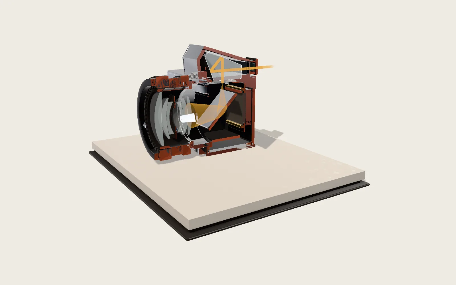 Plate C02The SLR CameraWhile you frame, a mirror behind the lens sends the light up into a prism. Press the release and the mirror lifts; two cloth curtains cross the film one after the other.
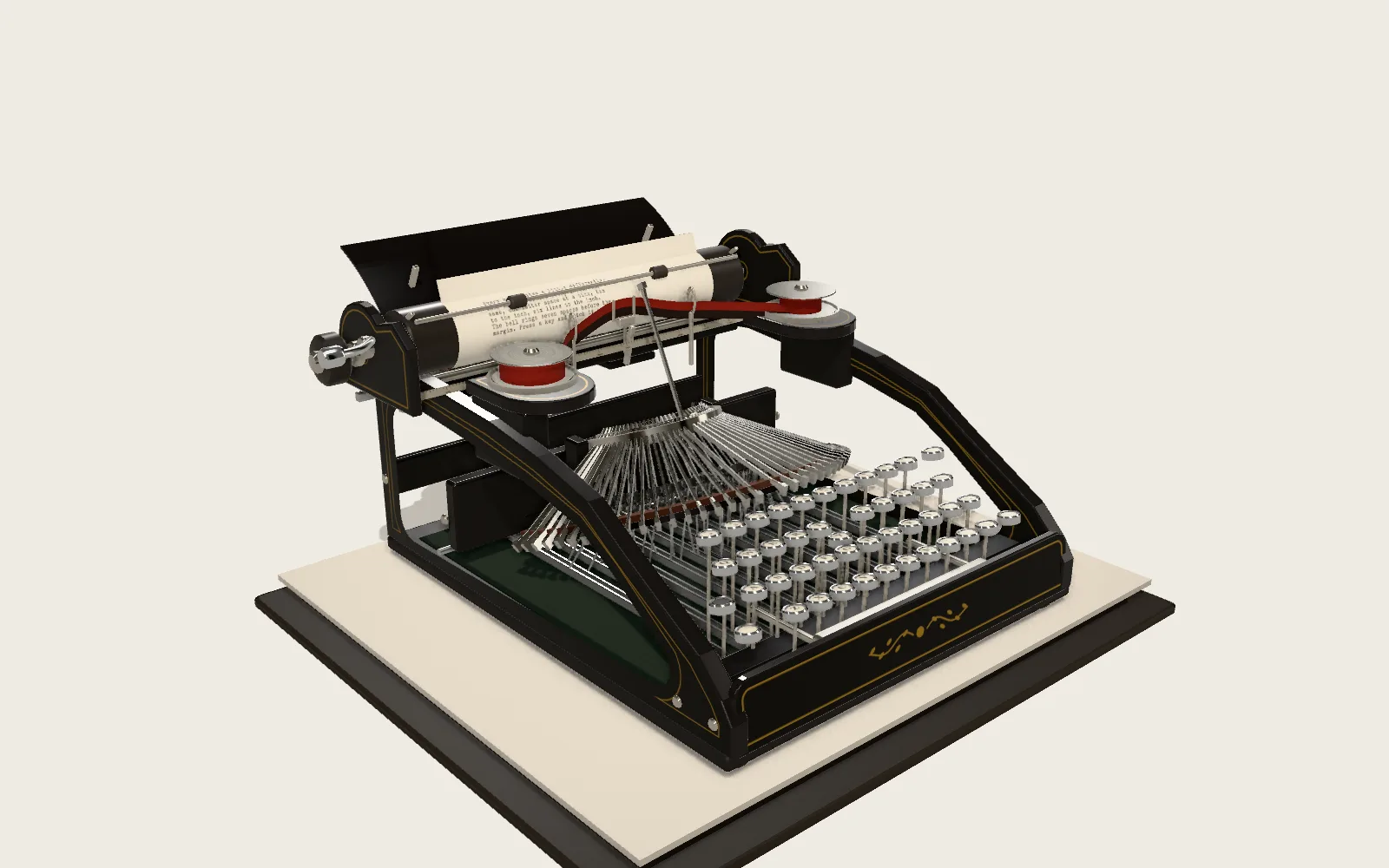 Plate C07The TypewriterPress a key and a typebar swings up and strikes the paper through the ribbon; let go and the carriage steps one space to the left.
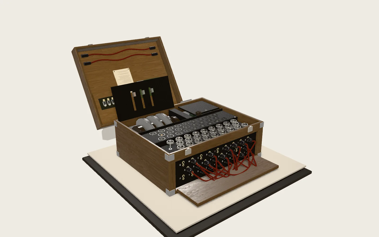 Plate C09The Enigma Cipher MachinePress a key and the rotors step first; the current runs through the plugboard, three rotors and a reflector and back, and another letter lights up.