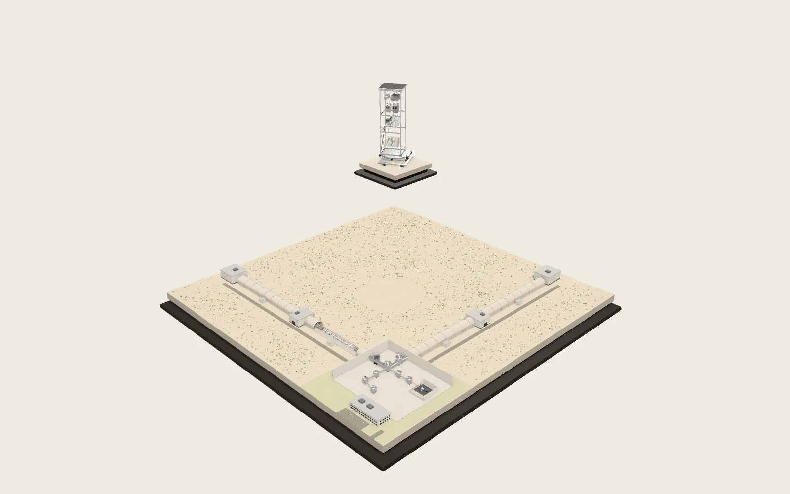
Turbofan Engine
Under a widebody’s wing, a turbofan gets about 85 % of its thrust from the air its fan pushes round the core. This is a cutaway model of one on a ground-run stand, about the size of a Boeing 787’s engines.
Scroll
1.2 Tonnes of Air a Second
At take-off this engine’s fan draws in about 1.2 tonnes of air every second. The fan is 2.9 m across and turns at 2,560 rpm; its blade tips move at about 390 m/s, faster than sound.
The gas entering the turbine is hotter than the melting point of the turbine blades’ alloy. Cooling passages inside the blades, a film of cooling air on their surface and a ceramic coat keep them whole.
The model’s cycle gives about 330 kN of take-off thrust, enough to hold up about 34 tonnes.
Air flow ≈ 1.2 t/s · tips ≈ 390 m/s · thrust ≈ 330 kN (this model)
Compress, Burn, Expand
The core runs a Brayton cycle. The fan root, four booster stages and a ten-stage high-pressure compressor squeeze the air about 44 times; it leaves at about 670 °C.
The combustor sprays in fuel and burns it, raising the gas to about 1,430 °C. The high-pressure turbine takes out exactly the work that drives the high-pressure compressor; the low-pressure turbine takes out the work that drives the fan and booster.
What is left leaves through the nozzle. The harder the squeeze and the hotter the burn, the more work the same fuel does.
Compression → heat at constant pressure → expansion → exhaust · OPR ≈ 44 · T4 ≈ 1,700 K (model)
Most Thrust Comes from the Fan
Of every 10.5 kg of air the fan takes in, about 1 kg goes through the core; the other 9.5 kg goes round it. That ratio is the bypass ratio.
The fan speeds the bypass air to only about 260 m/s; the core jet is faster, about 440 m/s. But there is far more bypass air, and it gives about 85 % of the thrust.
Thrust is the mass of air pushed back each second times the speed added to it. Pushing a lot of air gently uses less fuel than pushing a little air hard, which is why fans keep growing.
F = ṁ_bypass V_bypass + ṁ_core V_core · bypass ratio 9.5 · bypass ≈ 85 % (model)
Cut Open
Front to back: the intake, the fan and its containment case, four booster stages, the outlet guide vanes, the ten-stage high-pressure compressor, the annular combustor, two high-pressure turbine stages, seven low-pressure turbine stages, the exhaust plug.
Outside is the nacelle with its thrust reverser; inside it the core cowl; between the two runs the bypass duct. The cut faces are painted red, as on museum cutaways.
Stages: 1 + 4 / 10 / 2 / 7 (as on the GEnx-1B)
Two Shafts, Two Speeds
The fan, the booster and the low-pressure turbine sit on one long, thin shaft: N1. The high-pressure compressor and turbine sit on a second shaft around it: N2.
The shafts are not geared together; each finds its own speed. At take-off N1 turns at about 2,560 rpm and N2 at about 11,400. The big fan must turn slowly to keep its tips in check; the small compressor must turn fast to do its work.
GE and CFM engines have two shafts. Rolls-Royce’s Trents have three, adding an intermediate shaft. Pratt & Whitney’s PW1000G puts a reduction gearbox between the fan and its shaft.
N1: fan · booster · LP turbine | N2: HP compressor · HP turbine · shown 1:60
Twisted Blades
Each blade twists about 35° from root to tip. The tip moves much faster than the root; the twist meets the air at the right angle all along the blade.
The model has 20 hollow, wide-chord titanium blades of about 16 kg each. GE’s GEnx and GE9X use carbon-fibre composite blades with titanium leading edges.
The fan runs inside a containment case wrapped in aramid fabric. If a blade breaks, the case has to catch it.
20 blades · ≈ 35° twist root to tip · ≈ 16 kg each (model estimate)
Ten Stages
Each stage is a row of rotor blades and a row of stator vanes. The rotor speeds the air up; the stator turns that speed into pressure. One stage adds a little; ten together give the high-pressure compressor a ratio of about 23.
The air gets denser towards the back, so the passage narrows and the blades shorten. The section shows each stage’s disc: a rim holding the blades, a thin web, a thick bore.
The front stages are titanium. Towards the back the air is at five or six hundred degrees, and the stages are nickel alloy.
HP compressor 10 stages · ratio ≈ 23 · exit ≈ 670 °C (model)
Annular Combustor
The compressed air slows down and enters a ring-shaped combustor. A ring of fuel nozzles at its head (22 in the model) atomises the fuel and mixes it with air.
Only part of the air burns. The rest enters through holes and slots in the liner walls, cooling them and diluting the gas to a temperature the turbine can take.
The ring of pipe outside is the fuel manifold, feeding every nozzle.
Fuel ≈ 2.8 kg/s · gas ≈ 1,430 °C (model)
Hotter than Melting
The first high-pressure turbine blades are cast from a single-crystal nickel superalloy: the whole blade is one grain, with no grain boundaries to slide at high temperature.
Such alloys begin to melt at a little over 1,300 °C. In modern engines the gas entering the turbine is at about 1,600 to 1,700 °C; Rolls-Royce says its blades work in gas up to about 200 degrees above their alloy’s melting point.
Air from the compressor runs through winding passages inside each blade and leaves through rows of small holes, laying a film of cooler air over the surface. A ceramic thermal barrier coat about 0.25 mm thick covers it. The metal itself stays below its melting point.
Gas ≈ 1,600–1,700 °C · CMSX-4 solidus ≈ 1,340 °C · the metal stays cooler
Throwing a Blade
Before an engine is certified it must pass a fan-blade-out test: at its maximum permitted speed, a small charge cuts one fan blade off at its root.
US rule 14 CFR 33.94 requires the engine to contain the damage, without fire and without its mounts failing, and to keep running for at least 15 seconds unless it shuts itself down.
By the model’s numbers, the blade of about 16 kg leaves with about 470 kJ of kinetic energy, like a one-tonne car at 110 km/h. The rotor it leaves behind is out of balance by about 1 MN.
14 CFR 33.94 · CS-E 810 · ≈ 470 kJ (model estimate)
Real Engines
GEnx-1B (Boeing 787): fan 2.82 m, two shafts, 255–358 kN at take-off, bypass ratio about 9, take-off pressure ratio about 44–47.
Trent 1000 (Boeing 787): fan 2.85 m, three shafts, 265–360 kN, bypass ratio over 10, pressure ratio about 50.
GE90-115B (Boeing 777): fan about 3.25 m, 514 kN at take-off. GE9X (777X): fan 3.4 m, bypass ratio about 10, pressure ratio over 60.
LEAP-1A (A320neo): fan about 1.98 m, 107–143 kN, bypass ratio about 11.
Thrust: take-off ratings from the type certificate data sheets
Taken Apart
The parts slide apart along the engine’s axis. Rest the pointer on one and it is lifted out on its own and named.
Throttle
Open the throttle: N1 and N2 rise together, and the cycle model computes the thrust as you go. Thrust rises faster than fan speed: at 80 % N1 the model gives only about 70 % of take-off thrust.
Try thisPull the throttle back from take-off to 80 % N1: how much of the thrust is left, and why is it less than 80 %?
What the model leaves out
This is a generic large two-shaft turbofan, not a particular engine. Its stage counts follow the GEnx-1B; its fan blades are hollow titanium (as on the Trents); sizes, counts and shapes were chosen to show the structure. Accessory gearbox, pipes and harnesses, the thrust reverser’s cascades in detail and the pylon are left out. Thrust, flows and temperatures come from a 0-D Brayton cycle: sea level, static, ISA day; fan flow = this model’s fan face area × air density × axial speed (Mach 0.58 × N1); each compressor’s temperature rise ∝ its shaft speed squared; bypass ratio 9.5 (about 11 at idle); T4 scheduled from about 1,000 K at idle to 1,700 K at take-off; efficiencies fan 0.92, booster 0.89, HP compressor 0.87, HP turbine 0.90, LP turbine 0.92, nozzles 0.98; 5 % burner pressure loss; both nozzles fully expanded. It ignores cooling air, so its T4 is lower than a real combustor exit, which burns hotter and then mixes in cooling air. Spin is shown 1:60, the HP shaft a further 4 times slower.
Common misconceptions
A jet does not move by its exhaust “pushing on the air behind”: thrust is the reaction of the air the engine accelerates backwards, and most of it acts on the fan blades and casings. A high bypass ratio does not make the core unimportant: all the fan’s work comes from the core’s low-pressure turbine. Blades “running above their melting point” means the gas: the metal itself stays below it, thanks to cooling and coatings. The fan-blade-out test is not a failure demonstration but a test every engine type must pass to be certified.
Sources
- EASA TCDS IM.E.102: GEnx (stages, take-off thrust, rotor speeds)
- GE Aerospace: GEnx (111.1 in fan, 18 composite blades, bypass ratio, pressure ratio)
- EASA TCDS E.036: Trent 1000 (three-shaft, 2.85 m, thrust)
- Rolls-Royce: Trent 1000 (over 85 % of thrust from the fan)
- Rolls-Royce: Trent 1000 infographic (20 blades, bypass ratio, pressure ratio)
- EASA TCDS IM.E.002: GE90-115B
- GE Aerospace: GE90
- GE Aerospace: GE9X (134 in fan, bypass ratio, pressure ratio)
- EASA TCDS E.111: Trent XWB
- EASA TCDS E.110: LEAP-1A
- EASA TCDS IM.E.093: PW1100G-JM (geared fan)
- Rolls-Royce (2012): single-crystal blades in gas up to 200 degrees above their alloy’s melting point
- The Naked Scientists: a Rolls-Royce metallurgist on turbine cooling (film cooling, thermal barrier coatings)
- BAM: solidus of CMSX-4
- T. M. Pollock, S. Tin (2006): Nickel-Based Superalloys for Advanced Turbine Engines, J. Propulsion and Power
- 14 CFR 33.94: blade containment and rotor unbalance tests
- EASA CS-E 810: compressor and turbine blade failure
- ACJ E 810 (JAR-E): conditions for the blade-out test
- NASA TM-2009-215784 (Guynn et al.): component efficiencies and T4 for turbofan cycles
- Georgia Tech AE 4451: turbofan performance notes
Data
The engine’s geometry (flowpath, nacelle, fan, stages, stand) is ported and rewritten from the turbofan example in AirsupHQ/machine-skill (github.com/AirsupHQ/machine-skill), MIT licence, © 2026 Air Supply Technologies Inc. (Airsup); so are the section caps, heat tint and airflow streaks. Material presets, parts and the softbox studio of the site’s model kit are ported from the same project. The cycle model, the figures it gives and the words are the site’s own.
Follow the question
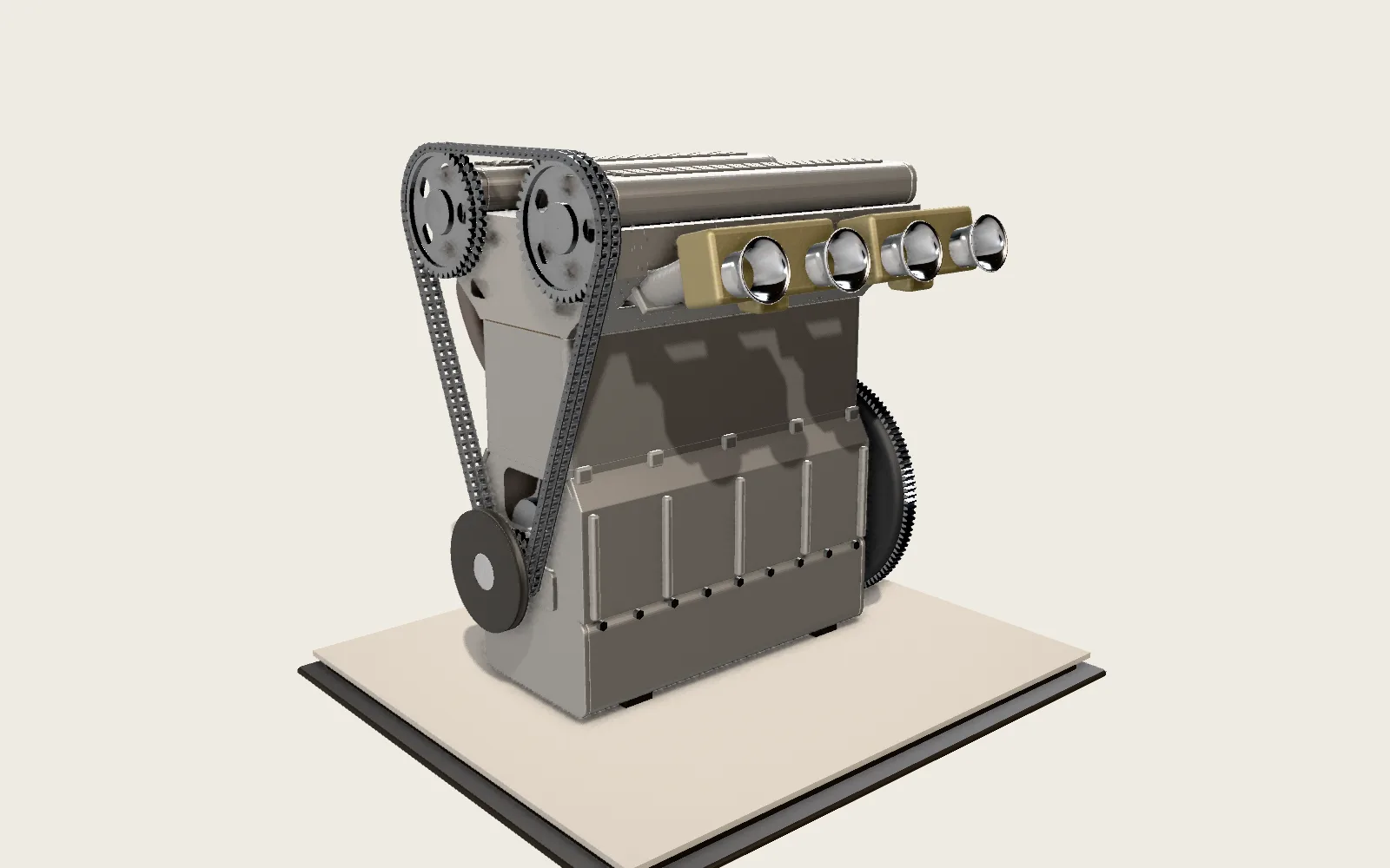 Plate C04The Four-Stroke EngineThe fuel burns inside the cylinder. The piston makes four strokes and the crank turns twice; in one of them, the burning gas drives the piston down.
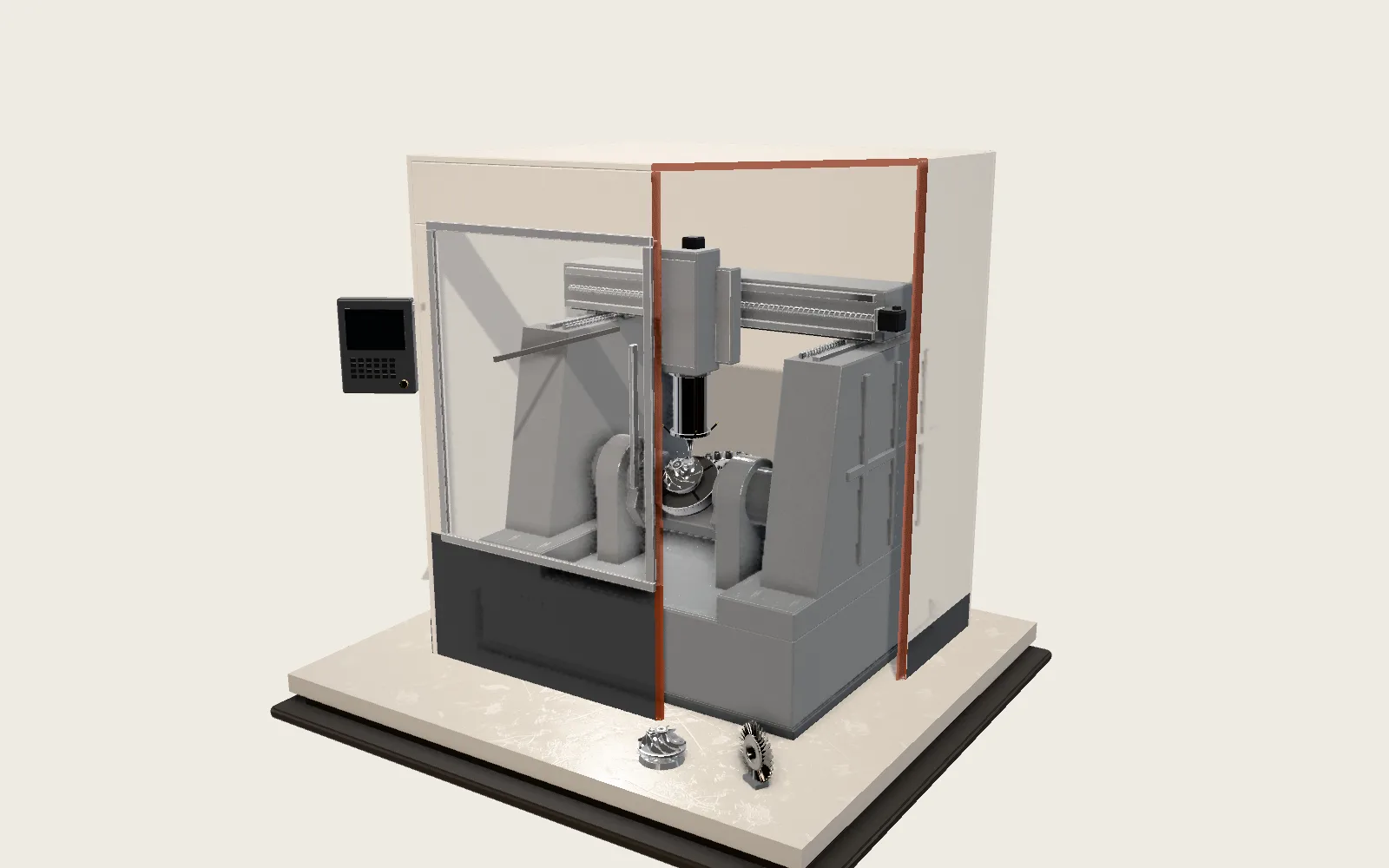 Plate F02Five-Axis Machining CentreThree straight axes move the spindle, two rotary axes turn the part, and all five move together to cut an impeller from a solid block of aluminium.