The Phased Array
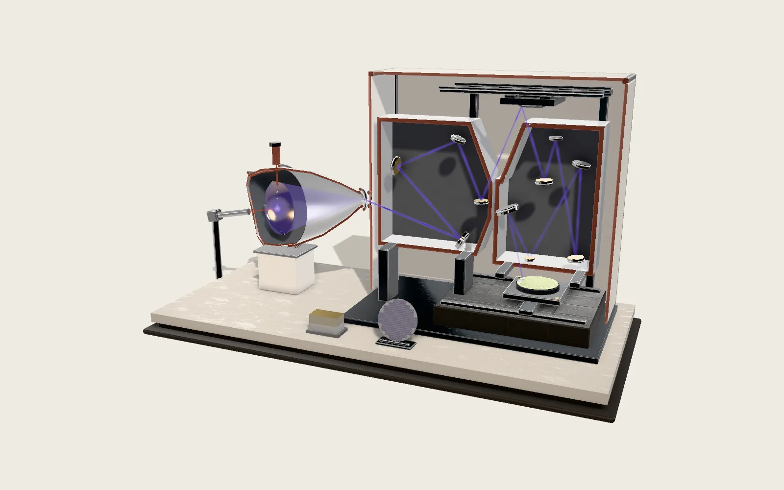
In radars, 5G base stations and satellite terminals there is an antenna that changes direction without turning: many small antennas send the same wave, and when their phases are staggered in order, the beam they add up to swings round. Here is a flat-panel terminal, cut open, and beside it a ripple tank whose light is the wave computed for the same arrangement.
Chapters · 11
- 01One Flat Panel, Any Direction in the Sky
- 02Many Small Waves Make One Beam
- 03Each a Little Later, and the Wavefront Tilts
- 04Half a Wavelength Apart
- 05More Elements, a Narrower Beam
- 06The Panel, Cut Open
- 07Layer by Layer
- 08Where Each Element’s Phase Comes From
- 09Where They Are Used
- 10Receiving Works the Same Way
- 11Laboratory
Scroll
One Flat Panel, Any Direction in the Sky
This panel carries 32 × 32 = 1,024 small gold squares, each one an antenna. Together they send the same wave, which adds up above the panel into a narrow beam.
Where the beam points is set not by turning the panel but by when each element sends. Change a set of numbers and the beam points elsewhere; nothing has to swing round in between.
With 32 elements in a row half a wavelength apart, the beam is about 3.2° wide. Panels like this can usually lean their beam 50° to 60° either side.
32 × 32 elements · spacing λ/2 · beam about 3.2° wide
Many Small Waves Make One Beam
On its own, each small antenna sends a wave that spreads every way: weak, with no direction.
Put many in a row and let them send together, and their waves meet and add. Straight ahead, the crests from every element arrive together and pile up: the wave is strongest there, the main beam. At a slant the paths differ, and crests meet troughs and cancel.
The tank on the right shows the same thing with a row of fine pins tapping the water. The bright lines are crests.
All in step: the beam is square to the row
Each a Little Later, and the Wavefront Tilts
Let each element send a little later than its left-hand neighbour, by a fixed phase step Δφ.
The later waves have not gone as far as the earlier ones, so the wavefront joining them leans. A wave always travels square to its front, so the beam turns.
The angle follows sin θ = Δφ·λ / (2π d), with d the spacing and λ the wavelength. A larger Δφ leans it further; its sign picks the side.
sin θ = Δφ · λ / (2π d)
Half a Wavelength Apart
The elements cannot be too far apart. Once the spacing passes λ / (1 + |sin θ|), a second beam as strong as the main one appears in another direction: a grating lobe.
The reason is that phase comes round in a circle: in that direction, neighbouring elements differ by exactly one whole wavelength, so they line up too.
With about half a wavelength between elements, no grating lobe appears at any angle. That is why a 28 GHz array has its elements about 5.4 mm apart.
No grating lobe: d < λ / (1 + |sin θ|)
More Elements, a Narrower Beam
The longer the row, the narrower the beam: about 0.886·λ / (N·d) radians wide. Twice the elements, half the width. Steered away from straight ahead, the beam widens by about 1/cos θ.
Either side of the main beam are rings of weak side lobes. With every element equally strong, the highest is about 13 dB below the main beam.
Making the middle elements stronger and the edges weaker (a taper) pushes the side lobes lower, at the cost of a slightly wider beam.
Width ≈ 0.886 λ / (N d) · uniform: first side lobe about −13 dB
The Panel, Cut Open
One corner of the panel is cut away to show its layers. On top is the white radome, which the radio waves pass through.
Below it: the gold patch antennas on green solder mask, the dielectric and the copper ground plane, the feed-network board, the beamforming chips, and an aluminium plate with fins to carry the heat away.
A patch is a little under half a wavelength long in the dielectric, so the higher the frequency, the smaller and denser the patches.
Layer by Layer
The layers move apart along the panel’s normal. Rest the pointer on one and it is lifted out on its own and named.
The gold traces on the feed board split in two, then in four, and so on, carrying the signal to every chip; each chip passes it on to its own patches.
Where Each Element’s Phase Comes From
In the beamforming chips, every element has its own phase shifter and amplifier. Here each chip serves 4 × 4 = 16 elements.
With “Show phases” on, each patch is coloured by its phase: along a row the colour turns step by step. That step is Δφ.
Digital beamforming instead sets each element’s phase in the digital signal, and can form several beams at once.
Phase of element n: −n · Δφ
Where They Are Used
5G millimetre wave: band n257 runs from 26.5 to 29.5 GHz, and at 28 GHz the wavelength is about 10.7 mm. A phone’s millimetre-wave antenna module is itself a small phased array, and a phone can hold up to four. One experimental 28 GHz array drives 64 antennas from 4 chips and steers its beams over ±50° in 1.4° steps.
Satellite terminals: Starlink’s user terminal is an electronic phased-array panel with a 110° field of view. It receives at 10.7 to 12.7 GHz and sends at 14.0 to 14.5 GHz (Ku band). The satellite crosses the sky; the panel stays still and its beam follows.
Radar: in an active electronically scanned array (AESA) every element has its own transmit-receive module, and the beam can point somewhere new between one pulse and the next. The US National Severe Storms Laboratory’s experimental phased-array weather radar has 4,864 elements and scans the whole sky in under a minute; today’s turning radars take four to six.
The first demonstration was in 1905: Braun’s assistants set three antennas in a triangle and let one send a quarter cycle late, and the waves leaned to one side. Swapping the antennas’ roles turned the direction.
Light can be steered the same way: an optical phased array does it for a lidar, with elements spaced on the scale of the light’s wavelength; most are still at the research stage.
λ = c / f · 28 GHz → 10.7 mm · 12 GHz → 25 mm
Receiving Works the Same Way
An antenna’s pattern is the same for sending and receiving (reciprocity). A wave arriving from one direction reaches the elements one after another; shift them by the same phase steps and add, and only signals from that direction pile up, while the rest cancel.
In an active array, sending and receiving go through different amplifiers, so reciprocity does not apply directly; but on receive each element is given its phase in the same way, and the pattern follows the same array factor.
So the same panel that points its beam at a satellite also listens only in that direction. Here the waves run backwards, converging on the panel.
Laboratory
Set the steering angle, the number of elements and the spacing. Show the phases, switch between the moving wave and its average strength, take the panel apart or cut it open.
Try thisSixteen elements steered to 30°: at what spacing does the first ghost beam appear, and in which direction?
What the model leaves out
The panel is a generic design, not a maker’s; its layers are thickened to be seen. The waves in the tank and over the panel are two-dimensional slices: a row of elements is a row of point sources, each sending a cylindrical wave that fades as 1/√r, and each column of the panel counts as one source in step. The water’s brightness is scaled by the main beam’s strength at that distance, so near and far crests are equally bright. The tank’s wavelength shrinks when needed so that the whole row of pins fits. The panel’s spacing stays at half a wavelength; the spacing slider changes only the tank and the chart. Real patches have their own element pattern, mutual coupling and two polarisations; none of these is computed here.
Common misconceptions
The beam is not rays from each element bundled together; it is one wave adding up with itself in space. A phased array has no moving parts, but the further it steers, the smaller its effective aperture: the beam widens and the gain falls, and most stop at around 60°. A grating lobe is not noise; it is another beam as strong as the main one. Low side lobes are not no side lobes. A phone’s millimetre-wave antenna is held to the same exposure limits as any other radio.
Sources
- BIPM: speed of light 299,792,458 m/s (defined)
- 3GPP TS 38.101-2 (ETSI copy), table 5.2-1: n257 26.5–29.5 GHz, n258, n260, n261 27.5–28.35 GHz
- Qualcomm, July 2018: QTM052 mmWave antenna module, a phased array with beamforming, steering and tracking; up to four per phone
- Sadhu et al., IEEE JSSC 2017 (IBM and Ericsson): a 28 GHz 32-element phased-array IC; 4 ICs, 64 dual-polarised antennas, ±50°, 1.4° steps
- Starlink Standard kit specification sheet: electronic phased-array antenna, 110° field of view
- FCC 18-38 (2018): SpaceX user terminals in Ku band, receive 10.7–12.7 GHz, send 14.0–14.5 GHz
- NOAA NSSL: the Advanced Technology Demonstrator, 76 panels, 4,864 radiating elements, a stationary antenna steered electronically
- NOAA NSSL: phased-array radar scans the sky in under a minute (the WSR-88D takes four to six)
- NASA UAVSAR: an active electronically steered array with its own transmit/receive modules, steering pulse to pulse
- Smolders, Visser and Johannsen, Modern Antennas and Microwave Circuits (phase steering, grating-lobe condition d/λ ≤ 1/(1+|sin θ|), half-power width 0.8858 λ/(K d cos θ), uniform side lobes, reciprocity)
- MIT OpenCourseWare 6.013, chapter 10: antenna arrays, array factor, beam scanning, reciprocal antennas
- NASA TM-81882: a rectangular patch resonates at about half a wavelength in the dielectric
- Karl Ferdinand Braun, 1909 Nobel lecture: directed transmission with three antennas, Strasbourg 1905
- Liu, Dong and Hu, APL Photonics 2026: integrated optical phased arrays, challenges and trends
Data
Band edges are from 3GPP TS 38.101-2 (ETSI copy); the speed of light from BIPM. The phone module follows Qualcomm’s QTM052 announcement (July 2018); the 28 GHz array follows Sadhu et al., IEEE Journal of Solid-State Circuits 2017 (IBM and Ericsson). The satellite terminal follows Starlink’s Standard kit specification sheet and the FCC’s 2018 authorisation of SpaceX (FCC 18-38). The weather radar follows NOAA’s National Severe Storms Laboratory; pulse-to-pulse steering follows NASA’s UAVSAR paper. Array theory (steering, grating lobes, beamwidth, side lobes, reciprocity) follows Smolders, Visser and Johannsen, Modern Antennas and Microwave Circuits (TU Eindhoven), and MIT OpenCourseWare 6.013, chapter 10; patch length follows NASA TM-81882. The 1905 three-antenna experiment is from Karl Ferdinand Braun’s 1909 Nobel lecture. Optical phased arrays follow Liu, Dong and Hu, APL Photonics 2026. The terminal, the ripple tank and every field on the page are the site’s own: the waves on the water and over the panel are summed from the elements on the GPU, and the chart is computed from the same numbers. The panel is a generic design, not a maker’s. The model kit’s parts and presets are ported from AirsupHQ/machine-skill (MIT licence, © 2026 Air Supply Technologies Inc.).
Follow the question
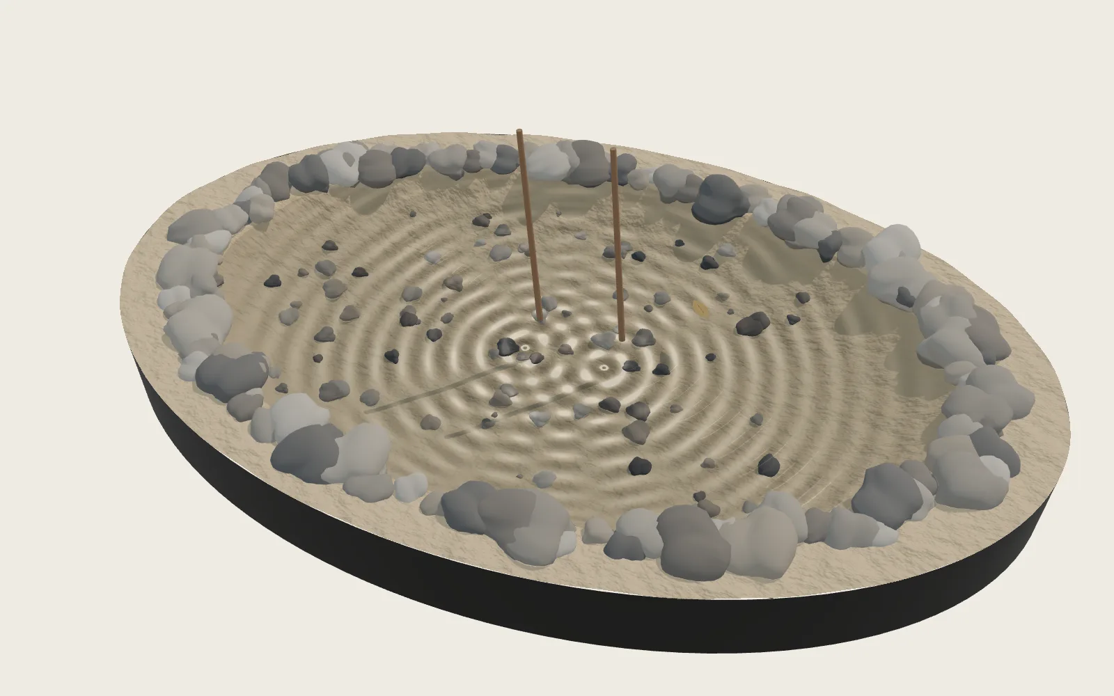 Plate 37When Two Ripples MeetDrop two stones in water and their rings of ripples pass straight through each other. In some places they cancel out, and the water there barely moves.
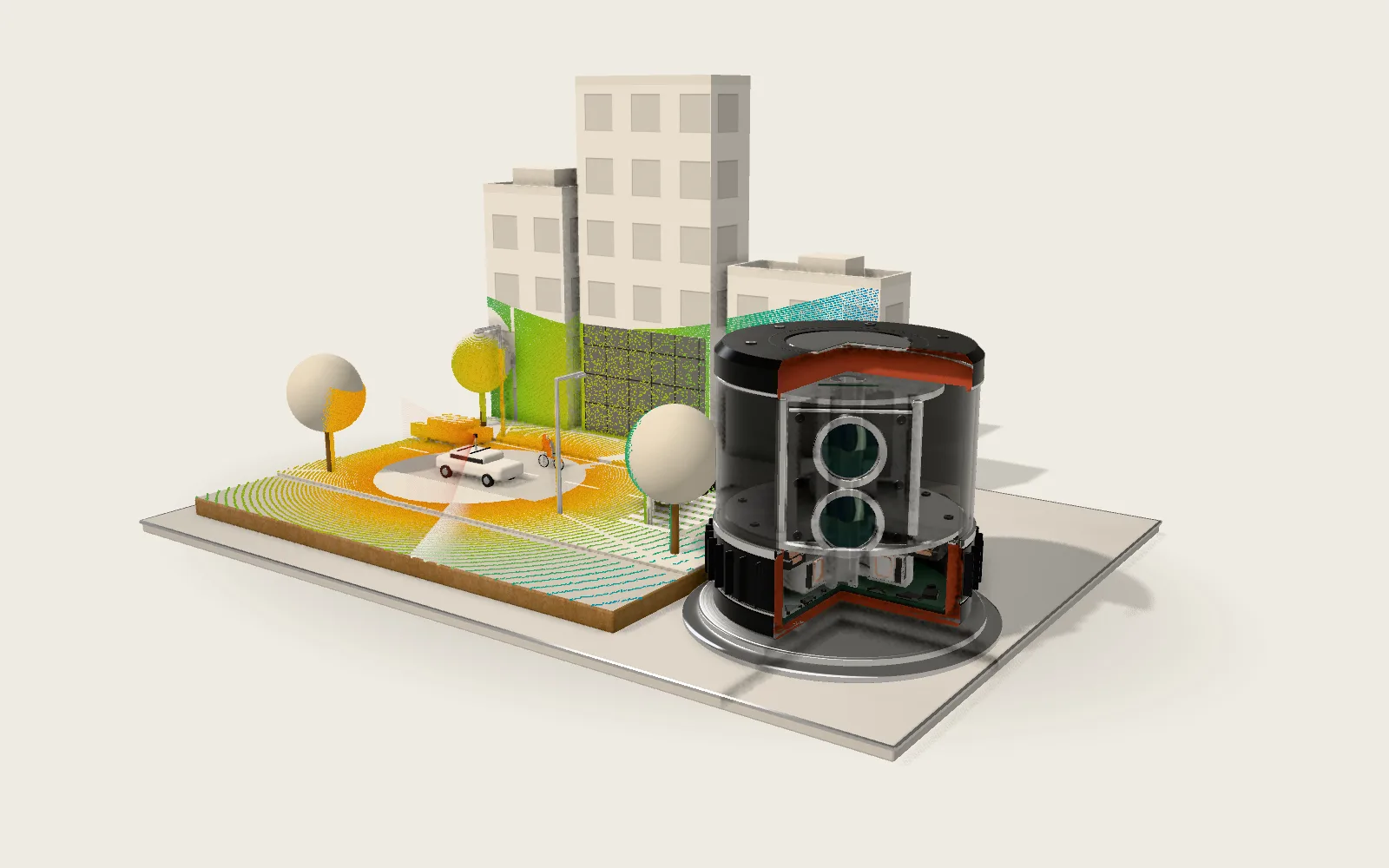 Plate F11LidarA lidar on a car’s roof times light: 6.67 nanoseconds there and back is one metre. 128 beams spin, and the street around turns into hundreds of thousands of points with coordinates.