Lidar
Self-driving cars and robots see in 3D with lidar: a laser pulse goes out, bounces back, and the time it took gives the distance. A column of lasers spins and measures over two million points a second. Here is a street model at 1 : 100, every point on its ground and walls computed along real beam angles, and beside it the sensor head at full size, cut open.
Chapters · 15
- 01Over Two Million Points a Second
- 02Timing Light
- 03Ring by Ring
- 0416, 32, 64, 128 Channels
- 05The Head, Cut Open
- 06A Column of Lasers, One Lens
- 07One Detector for Each Beam
- 08Turning, Powering, Knowing Where It Points
- 09900 or 1,550 Nanometres
- 10Lidars That Don’t Spin
- 11Speed, Measured Directly
- 12Fog and Black Paint
- 13Ghosts Behind the Glass
- 14Taken Apart
- 15Laboratory
Scroll
Over Two Million Points a Second
The sensor on the car’s roof has 128 beams. Its optical head turns 10 times a second, and each turn is split into 2,048 directions; in each direction all 128 beams measure once. That is 2,621,440 points a second.
In one turn, everything within 360° around and about 42° up and down becomes a point with coordinates. Datasheets give the range accuracy as about ±2 to 3 cm (typical), out to more than a hundred metres.
The street is a model at 1 : 100. A point’s colour shows how far it is from the sensor: red near, violet far.
128 channels × 2,048 × 10 turns/s = 2,621,440 points/s (single return)
Timing Light
Ranging is timing. A laser sends out a very short pulse of light; it bounces off something and comes back, and the detector records how long the trip took.
Distance = speed of light × time ÷ 2. Divided by 2 because the light went there and back.
Light travels about 30 cm in a nanosecond. For something 1 m away the round trip is about 6.67 ns; to tell 1 cm apart, the timing must be good to about 67 picoseconds.
The pulse here follows its real path, slowed down about 30 million times.
d = c·t / 2 · 1 m ↔ 6.67 ns · 1 cm ↔ 66.7 ps
Ring by Ring
One pulse measures one point. To measure all around, the optical head has to spin. 10 or 20 turns a second is common.
The head holds not one beam but a vertical column of them, each at a fixed elevation, from twenty-odd degrees down to a dozen or more up. In one turn, each beam draws a ring of points around the car.
On flat ground the rings are concentric circles. The beam 21.2° down, starting 2.2 m up, lands 5.7 m away; the nearer a beam is to level, the larger and sparser its ring.
Radius of a ring on the ground = mounting height ÷ tan(depression)
16, 32, 64, 128 Channels
More channels, denser in the vertical. With 16, neighbouring beams are 2° apart: at 20 m, two rings are about 70 cm apart. With 128 they are about 0.33° apart: about 12 cm.
A faster spin refreshes the view more often but spreads each turn’s points thinner, because each beam fires a fixed number of times a second. A VLP-16 at 10 turns a second has a point every 0.2° across; at 20 turns, every 0.4°.
Four common layouts: 16 channels about 300,000 points a second, 32 about 700,000, 64 about 1.3 million, 128 about 2.6 million (single return).
VLP-16 · HDL-32E · HDL-64E S3 · OS1-128 (datasheets)
The Head, Cut Open
The sensor head at full size, cut open: about 10 cm across, like common 16- to 128-channel products.
The housing is black anodised aluminium. The dark glass band in the middle is the window the light passes through. The housing stays still; the optical head inside the window turns.
From the bottom: main board, motor, wireless power coils, encoder disc, the optical head (upper lens sends, lower lens receives), cap. The cut faces are red, as on museum cutaways.
A Column of Lasers, One Lens
The sending side: a column of lasers sits in the focal plane of the upper lens.
The lens turns position into direction. The further a laser sits from the lens axis, the more its beam is bent; one above the axis sends its beam down, one below sends it up. That fixes every beam’s elevation.
Each beam fires about twenty thousand times a second. Near-infrared light is invisible; it is drawn here as fine red lines.
Elevation = −arctan(height off the axis / focal length)
One Detector for Each Beam
The receiving side: the lower lens focuses the returning light onto a column of detectors. Light coming back from a given elevation lands on the matching detector, so each beam has its own.
The returning light is faint. The detectors must respond to very few photons: avalanche photodiodes (APDs) or arrays of single-photon avalanche diodes (SPADs) are common.
A baffle between the two sides keeps outgoing light from leaking straight into the detectors.
Turning, Powering, Knowing Where It Points
The optical head runs on bearings, turned by the motor beneath. 10 turns a second is 600 rpm; 20 is 1,200.
The turning part needs power and has to send its data down. One way is a slip ring, brushes pressing on turning copper rings. The other, drawn here, is a pair of coils across an air gap that pass power over by induction, like a transformer, with the data also crossing without contact.
An encoder tells the system where the head is pointing: a disc with fine slots turns with it, and a read head counts the slots going by. Every point’s azimuth comes from it.
10 turns/s · 2,048 steps a turn → 0.176° a step
900 or 1,550 Nanometres
Most automotive lidars use near-infrared light around 900 nm: 865, 903 and 905 nm in the datasheets cited here. Silicon detectors are sensitive there, cheap, and can be made into large arrays. Silicon only responds to light below about 1,100 nm.
Others use 1,550 nm. Light at this wavelength is absorbed mainly in the front of the eye (cornea, aqueous humour, lens) and is not focused onto the retina, so the safety limits allow much more power and the sensor can reach further. The cost: silicon does not respond to it, and detectors of indium gallium arsenide (InGaAs) are needed, which are dearer.
Both are built as Class 1 laser products under IEC 60825-1: safe for the eyes under reasonably foreseeable conditions of use.
Silicon: below about 1.1 µm · InGaAs: about 0.95–1.7 µm (Hamamatsu)
Lidars That Don’t Spin
A spinning head has a motor and bearings that wear, and it takes room. There are three main ways to do without it.
MEMS mirror: a tiny mirror on a chip swings back and forth, sweeping the beam across the view. Still a moving part, but a very small one.
Flash: light up the whole view at once and catch it with a two-dimensional detector array, like a camera taking a photo. No moving parts, but the light is spread thin, so the range is usually shorter.
Optical phased array (OPA): many emitters; adjust the phase between them and the beam steers, as in a phased-array radar. Fully solid state; a 2020 review said there was no commercial product yet.
Speed, Measured Directly
Everything so far is pulsed: timing the light. An FMCW (frequency-modulated continuous-wave) lidar sends no pulses. It sends light whose frequency keeps sweeping, and mixes what comes back with what it is sending now; the difference in frequency gives the distance.
If the target moves, the returning light also carries a Doppler shift f = 2v/λ. At 1,550 nm, 1 m/s along the line of sight is about 1.29 MHz. So each point carries its speed as well as its position. FMCW lidars typically work near 1,550 nm.
The points here are coloured that way: red for coming towards the sensor, blue for going away, grey for still.
f_D = 2v / λ · 1 m/s at 1,550 nm ≈ 1.29 MHz
Fog and Black Paint
Fog droplets scatter light every way. The light crosses the fog twice, and the echo fades exponentially. When visibility drops to a few tens of metres, the distant points go first.
Some light is thrown straight back by droplets close to the sensor, making a cloud of false points around the car (grey).
Some black car paints reflect only a few per cent of near-infrared light; the echo is weak, and such a car goes early too. That is why datasheets state the reflectivity: an Ouster OS1 reaches 170 m on an 80 % target and 90 m on a 10 % one.
As an echo nears the threshold, the timing gets less certain and the points jitter back and forth.
Two-way loss e^(−2αR) · α ≈ 3.912 / visibility
Ghosts Behind the Glass
Smooth glass is a mirror. A beam hits the shop window, reflects to something else, and comes back the same way. The sensor knows only the time; it assumes the light went straight along its own line, and puts the point behind the glass, where there is nothing.
Here the model is hidden and only the points remain. The magenta points behind the shop window are such “ghosts”, from light that took a longer path. A wet road does the same, putting points below the ground.
Processing software finds and removes them with geometry such as mirror symmetry.
Taken Apart
The head’s parts slide apart along its axis. Rest the pointer on one and it is lifted out on its own and named.
Laboratory
Set the channels, the spin and the fog. Show only the points, or take the head apart or cut it open. The spin is shown 1 : 40.
Try thisMove from 16 channels to 128: at 20 m, how far apart are two neighbouring rings before and after? Thicken the fog: which car disappears first?
What the model leaves out
The sensor head is a generic design, not a maker’s; its sizes are estimated from common products. The four layouts’ elevations are spread evenly over the ranges the datasheets give (real ones are not always even), and all beams fire together at each azimuth (real ones stagger them). The street is a simplified 1 : 100 model; only its solids return points, and the car carrying the sensor is left out; normally only points inside the model’s footprint are shown. Echo strength follows diffuse reflection, the square of the distance and the fog’s two-way loss, with the threshold set so that a 10 % target is just seen at the rated range; the fog’s near false points and the range jitter are illustrative. Fog loss is estimated from visible-light visibility. The spin is slowed 1 : 40 and the pulse about 30 million times; the pedestrian’s and cyclist’s speeds are illustrative.
Common misconceptions
Lidar measures distance and direction, not colour; the points are coloured by distance. A point cloud is not a photograph: each point is one range measurement. Near-infrared light is invisible, but invisible is not absent: eye safety comes from Class 1 limits, not from not seeing it. That 1,550 nm allows more power does not make any power safe; the front of the eye has limits too. FMCW measures speed along the line of sight; something crossing sideways shows almost none. Studies disagree on which wavelength does better in fog, so the page does not say.
Sources
- Velodyne VLP-16 datasheet (16 channels, ±15°, 5–20 Hz, ~300,000 points/s, ±3 cm, 903 nm, Class 1)
- Velodyne VLP-16 user manual (0.2° at 10 Hz; flight time halved, times the speed of light)
- Velodyne HDL-32E datasheet (+10.67° to −30.67°, ~695,000 points/s)
- Velodyne HDL-64E S3 datasheet (+2° to −24.9°, ~1,300,000 points/s, ±2 cm)
- Ouster OS1 Rev7 datasheet (128 channels, ±21.2°, 2048 × 10 Hz, 170 m at 80 % / 90 m at 10 %, 865 nm)
- Ouster OS1 Rev6 datasheet (128 channels, 2,621,440 points/s single return)
- Hesai Pandar128E3X user manual (905 nm, 200 m at 10 % reflectivity)
- MicroVision IRIS datasheet (1,550 nm, InGaAs receiver, Class 1)
- BIPM: speed of light 299,792,458 m/s (defined)
- Li & Ibanez-Guzman 2020, IEEE Signal Processing Magazine: range equation, MEMS / flash / OPA, APDs and SPADs, wavelengths
- ICNIRP 2013 laser exposure limits: 400–1,400 nm harms the retina; above 1,400 nm mainly the cornea
- Hamamatsu: cut-off wavelength λc = 1.24 / Eg; InGaAs about 1.7 µm
- NASA NTRS: linear FMCW laser radar for range and velocity (v = f_d λ / 2)
- Bijelic et al. 2018: lidar in fog, droplet clutter around the car
- Heinzler et al. 2019: weather and automotive lidar
- Yun & Sim 2018, CVPR: removing reflections from glass in point clouds
- US patent 9,207,323: a wet road as a mirror, points below the surface
Data
Channel layouts, rates, ranges and wavelengths are from the makers’ datasheets and manuals: Velodyne VLP-16, HDL-32E and HDL-64E S3 (now distributed by Ouster), Ouster OS1 (Rev6, Rev7), Hesai Pandar128E3X, and the MicroVision (formerly Luminar) IRIS. Solid-state scanning and detector choices follow Li and Ibanez-Guzman, “Lidar for Autonomous Driving”, IEEE Signal Processing Magazine 2020; eye-safety physics follows the ICNIRP 2013 laser guidelines; fog clutter follows Bijelic, Gruber and Ritter (IEEE IV 2018); glass ghosts follow Yun and Sim (CVPR 2018). The street, the sensor head and every point of the cloud are the site’s own: each point is a beam fired along a layout’s channel angles at the street model and timed. The head is a generic design, not a maker’s. The model kit’s parts and presets are ported from AirsupHQ/machine-skill (MIT licence, © 2026 Air Supply Technologies Inc.).
Follow the question
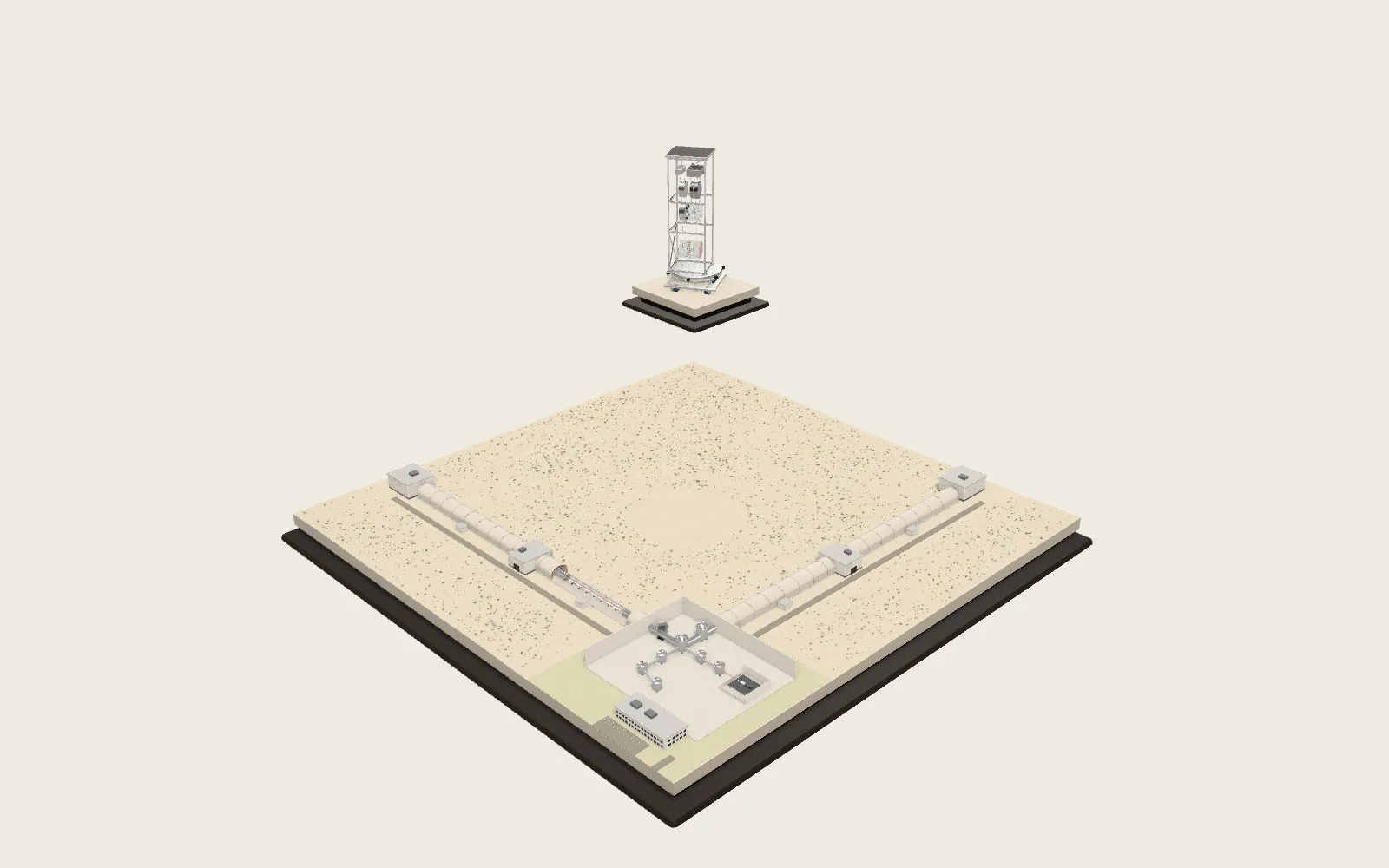 Plate F08The Gravitational-Wave InterferometerTwo arms 4 km long measure changes in length more than ten thousand times smaller than a proton. In 2015 it recorded, for the first time, the gravitational waves from two black holes merging.
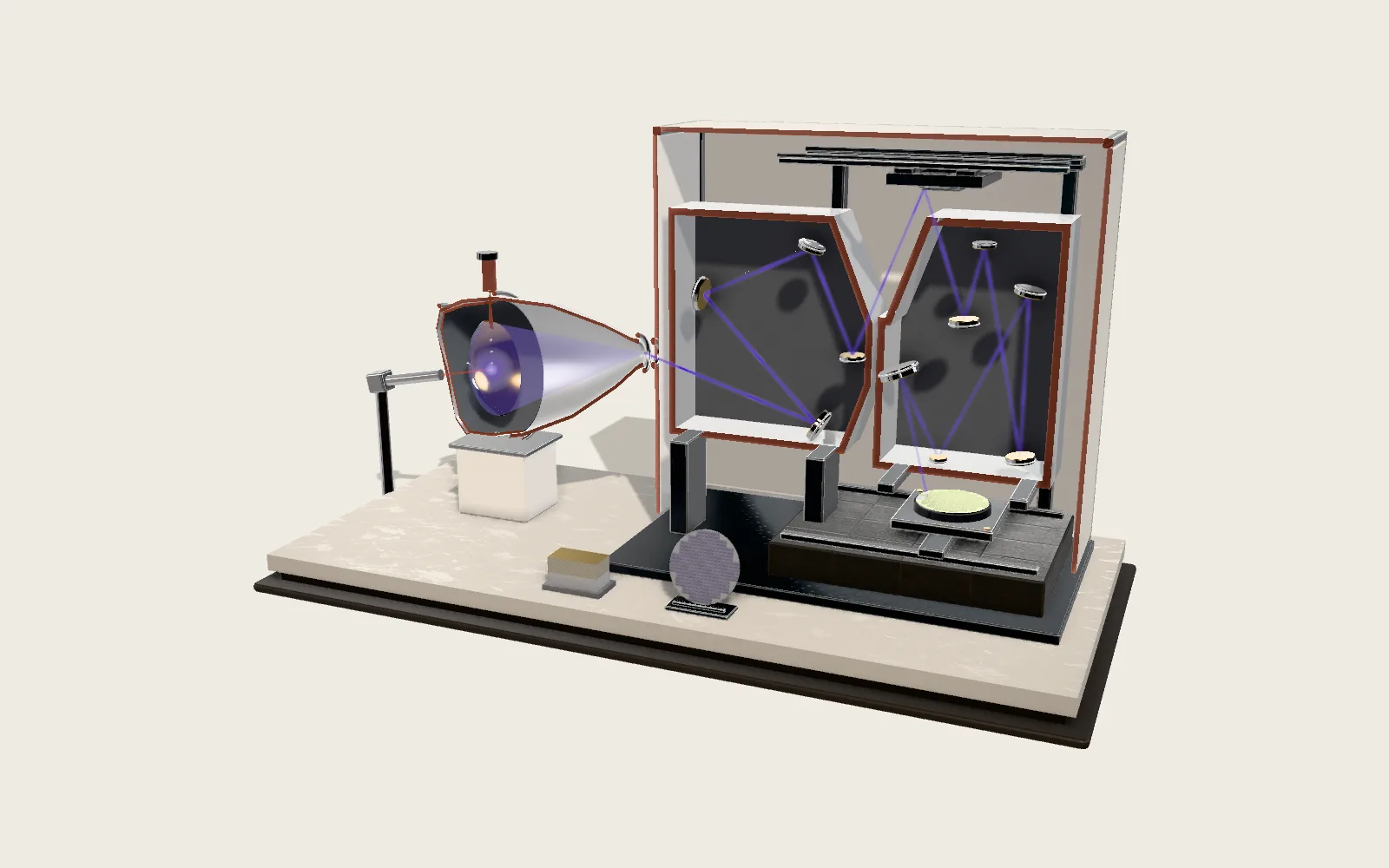 Plate F01EUV Lithography MachineLight 13.5 nm long prints a chip’s circuits on silicon, four times smaller than the mask. It comes from tin droplets turned to plasma, and travels only by mirrors.